
Blast resistant shelter and method of assembly

Active Publication Date: 2019-04-16
SOUTHERN COMFORT SHELTERS INC
View PDF36 Cites 0 Cited by
  • Summary
  • Abstract
  • Description
  • Claims
  • Application Information

AI Technical Summary

Benefits of technology

The patent text describes a blast resistant shelter that can be used to accommodate personnel at or near a process unit during a turnaround. The shelter is designed to withstand structural loads caused by a blast wave emanating from the process unit. The technical effects of this invention include providing a safer workplace for personnel, reducing the risk of damage or injury from blast waves, and minimizing the need for costly additional anchoring of the frame. The blast resistant shelter meets industry standards for blast resistance and is assembled using a frame and canopy. The canopy can be omitted from view in some embodiments. The shelter includes trusses and wall girts to withstand the structural loads of a blast wave. The shelter also includes blast panels that pivot or pivot up to a certain angle to allow for the blast wave to pass through. The patent text also includes time-lapse views of the blast panels in an assembled state and during the encounter of a blast wave.

Problems solved by technology

Failure to comply with the API's Recommended Practice 756 may result in excessive loading imparted on the frame of the shelter by the blast wave.
In severe cases, this excessive loading on the frame may cause significant structural damage or collapse.
Moreover, this excessive loading on the frame may necessitate costly additional anchoring of the frame.

Method used


Image

  • Blast resistant shelter and method of assembly
  • Blast resistant shelter and method of assembly
  • Blast resistant shelter and method of assembly

Examples


Embodiment Construction

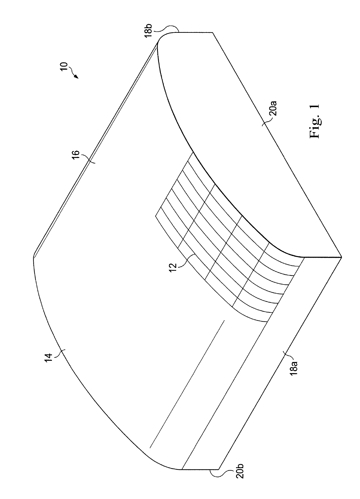
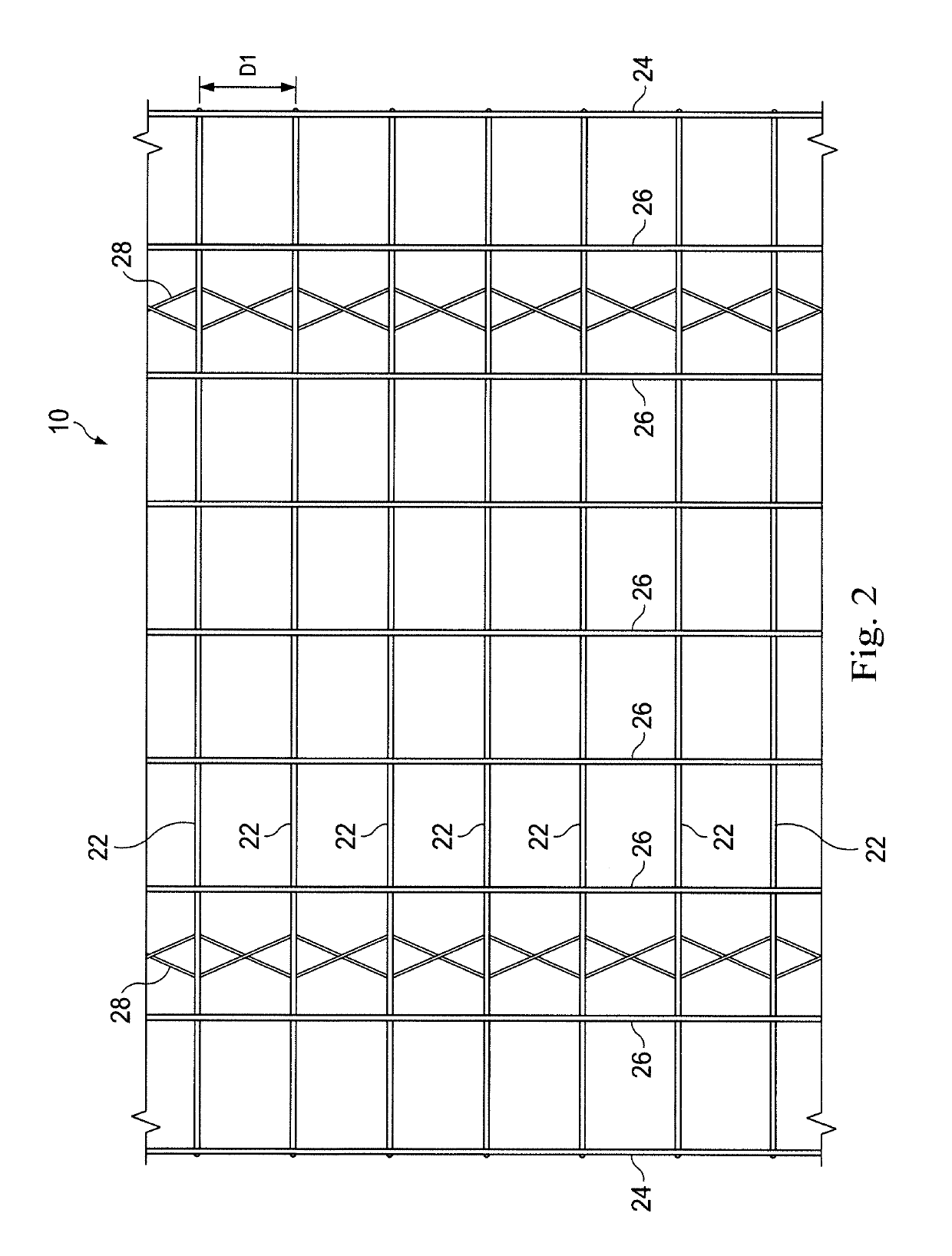
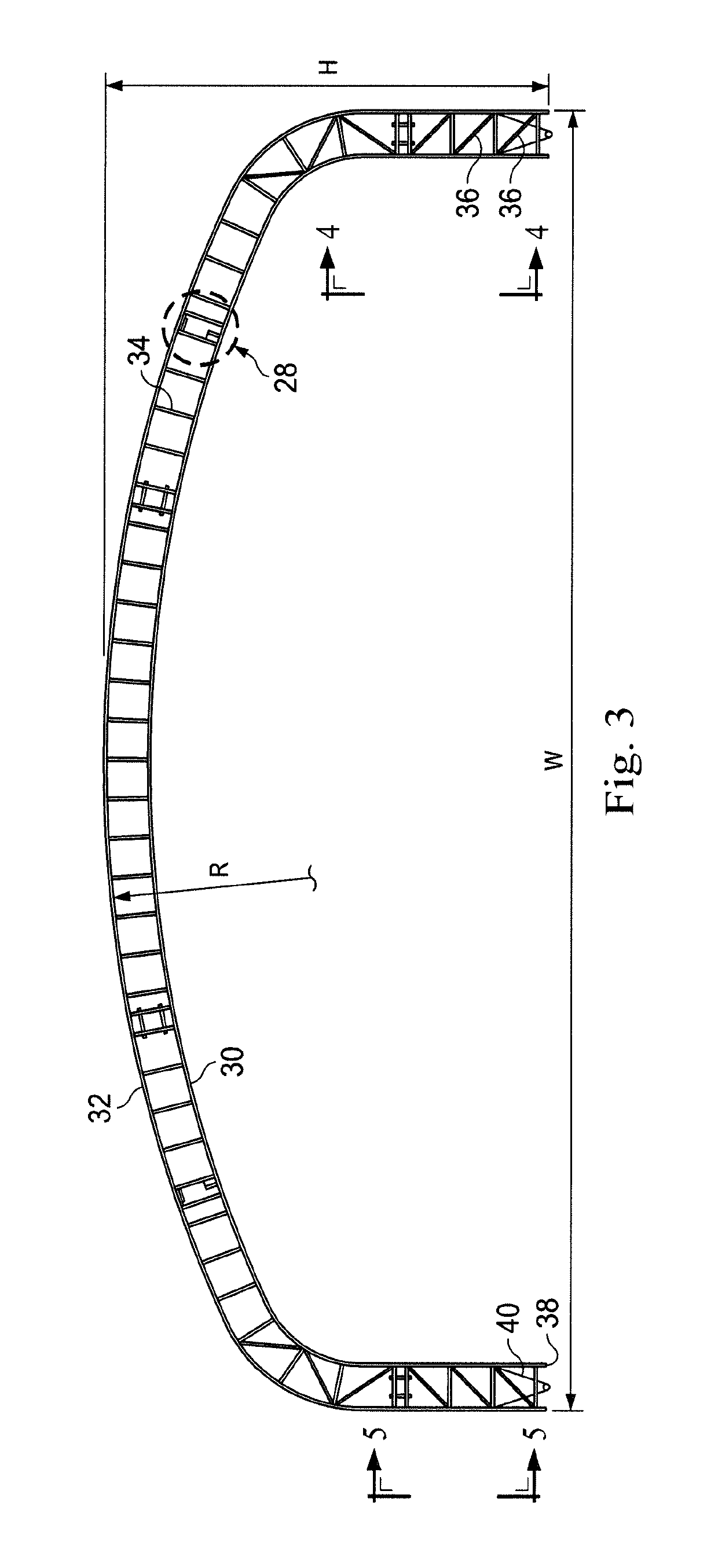
[0019]Referring initially to FIGS. 1 and 2, a blast resistant shelter is generally referred to by the reference numeral 10. FIG. 1 is a perspective view of the blast resistant shelter 10, which includes a frame 12 and a canopy 14. The frame 12 and the canopy 14 together define a roof 16, walls 18a and 18b, and gable ends 20a and 20b. The frame 12 includes a plurality of structural members such as, for example, trusses 22. The trusses 22 are spaced apart by a dimension D1, as shown in FIG. 2's top plan view of the blast resistant shelter 10 (with the canopy 14 omitted from view). In some embodiments, the trusses 22 are spaced apart in a substantially parallel relation. In some embodiments, the dimension D1 is approximately 4′ (feet). The trusses 22 are interconnected by a plurality of purlins including, for example, eave purlins 24 and roof purlins 26. The eave purlins 24 and the roof purlins 26 are spaced in a substantially perpendicular relation with the trusses 22 and, in combinat...


PUM


Abstract

A method and apparatus according to which a blast resistant shelter is assembled. The blast resistant shelter includes first and second structural members, a third structural member coupled to the first and second structural members, a first airway adjacent the third structural member, and a first blast panel pivotably mounted to the third structural member and adapted to pivot thereabout in response to a blast wave. In a first configuration, the first blast panel is detachably connected to a first portion of the blast resistant shelter and prevented from pivoting about the third structural member so that the first blast panel obstructs air flow through the first airway. In a second configuration, in response to the blast wave, the first blast panel is detached from the first portion of the blast resistant shelter and permitted to pivot about the third structural member to permit air flow through the first airway.

Description

CROSS-REFERENCE TO RELATED APPLICATION[0001]This application claims the benefit of the filing date of, and priority to, U.S. Application No. 62 / 484,482, filed Apr. 12, 2017, the entire disclosure of which is hereby incorporated herein by reference.TECHNICAL FIELD[0002]This disclosure relates in general to shelters used to accommodate personnel at or near a process unit during a turnaround and, in particular, to a blast resistant shelter and method of assembly.BACKGROUND[0003]A shelter may include a canopy draped over, and coupled to, a frame. If such a shelter is to be used to accommodate personnel at or near a process unit during a turnaround, it must comply with industry standards such as, for example, the American Petroleum Institute's (“API”) Recommended Practice 756. Such industry standards require the shelter to withstand structural loads that could be imparted by a blast wave emanating from the process unit. Failure to comply with the API's Recommended Practice 756 may result...

Claims


Application Information

Patent Timeline
IPC IPC(8): E04B1/34E04B1/32E04B1/344E04B1/19E04B1/24E04B1/342E04B1/92E04H9/04E04F13/00
CPCE04B1/3448E04B1/19E04B1/24E04B1/3205E04B1/92E04H9/04E04B1/342E04F13/002E04B2001/199E04B2001/3252E04H9/10E04B1/98Y02A50/00
Inventor DIXON, ROBERT C.
Owner SOUTHERN COMFORT SHELTERS INC
Learn More