Pick, in particular a round shaft pick

a pick and round shaft technology, applied in the field of picks, can solve the problems of multiple wear cycles of the pick holder, the wear of the support element and the pick holder in the region of the seating surface or the wear surface, etc., and achieve the effects of improving the rotatability of the support element, and reducing the wear of the pick

Active Publication Date: 2019-04-16
BETEK
View PDF10 Cites 7 Cited by
  • Summary
  • Abstract
  • Description
  • Claims
  • Application Information

AI Technical Summary

Benefits of technology

[0008]In the mounting position, the support element rests with its seating surface on a wear surface of a pick holder. When new, the groove releases the associated edge region of the pick holder, which leads to the support element being supported in a flat manner and to free rotatability. As a result of stress during use, the support element and the pick holder wear in the region of the seating surface or the wear surface. In this case, a circumferential bead is generated on the pick holder in the region of the groove. The bead is generated as a result of the support element wearing away the wear surface of the pick holder as a consequence of rotation of the pick and of the support element. By way of the bead, the support element receives additional lateral guiding, as a result of which, for example, jamming of the support element and consequently one-sided and consequently quick wearing of the support element and of the pick can be reliably avoided. As a result of the groove and of the region of the pick holder worked into the groove, a labyrinth-like sealing region is formed which reduces the ingress of waste material into the region of the pick shaft. Consequently, the wear is even reduced in the region and the free rotatability of the pick is improved. The depth of the groove of at least 0.3 mm ensures reliable lateral guiding as well as a noticeable reduction in the entry of waste material.
[0017]The rotatability, in this case, can be improved, in particular, as a result of the rounding portion being formed by a circular arc portion with a second radius within a range of between 0.2 mm and 25 mm and in a particularly preferred manner is 1.0 mm.

Problems solved by technology

As a result of stress during use, the support element and the pick holder wear in the region of the seating surface or the wear surface.
As a result, the pick holder can weather multiple wear cycles of the pick.

Method used


Image

  • Pick, in particular a round shaft pick
  • Pick, in particular a round shaft pick

Examples


Embodiment Construction

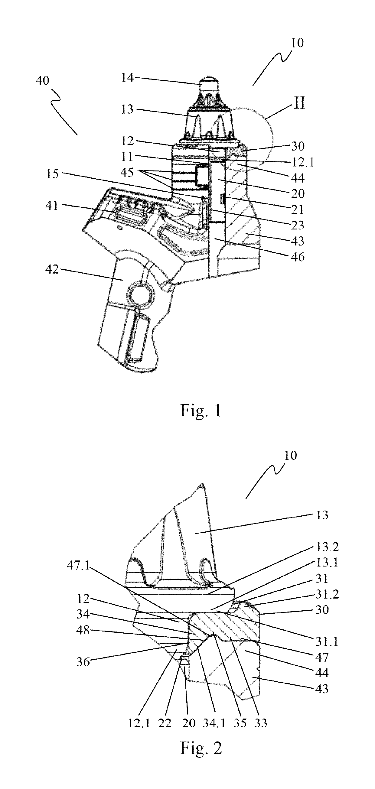
[0025]FIG. 1 shows a side view of a pick 10 in its mounting position on a pick holder 40, a sectional representation of part of the pick holder 40 being shown. The pick 10 is realized as a round shaft pick. It comprises a pick head 13 which merges into a pick tip 14, consisting of hard material, for example, hard metal. To this end, a bowl, into which the pick tip 14 is soldered, is worked into the pick head 13 on the end. On the side situated opposite the pick tip 14, the pick head 13 merges into a cylindrical centering portion 12 which, after a tapering region 12.1, merges into a cylindrical pick shaft 11. The pick head can also merge directly into the pick shaft 11 if the tapering region is dispensed with. The pick shaft 11 in the representation is predominantly concealed by a holding attachment 43 of the pick holder 40 as well as by a fastening sleeve 20. A circumferential groove 15 is inserted into the pick shaft 11. The pick 10, with its pick shaft 11, its pick head 13 and its...


PUM


Abstract

The present invention relates to a pick, in particular, a round shaft pick, having a pick head and a pick shaft, having a support element which has a centring lug on the underside thereof, wherein the centring lug has a centring surface which extends inclined with respect to the central longitudinal axis of the pick and merges into a seat surface. To this end circumferential channel according to the present invention is disposed in the transition region from the centring surface to the seat surface and the depth of the channel relative to the seat surface is greater than or equal to 0.3 mm. The pick has an optimised rotatability and thus a low wear.

Description

CROSS REFERENCE TO RELATED APPLICATIONS[0001]This application is a continuation of International Application No. PCT / EP2015 / 055263 filed Mar. 13, 2015, which designated the United States, and claims the benefit under 35 USC § 119(a)-(d) of German Application No. 10 2014 104 040.6 filed Mar. 24, 2014, the entireties of which are incorporated herein by reference.FIELD OF THE INVENTION[0002]The present invention relates to a pick, in particular, a round shaft pick, having a pick head and a pick shaft, having a support element which comprises a protruding centering attachment on its bottom surface and wherein the centering attachment comprises a centering surface which extends at an angle with respect to the center longitudinal axis of the pick and merges into a seating surface.BACKGROUND OF THE INVENTION[0003]A pick of this type is disclosed in DE 37 01 905 C1. In this case, the fastening sleeve is realized as a clamping sleeve which is formed from a resilient elastic material, for exa...

Claims


Application Information

Patent Timeline
Patent Type & Authority Patents(United States)
IPC IPC(8): E21C35/19E21C35/197
CPCE21C35/197E21C35/19
Inventor KAMMERER, KARLFRIEDERICHS, HEIKO
Owner BETEK
Why Eureka
Try Eureka