Duct mounted sound attenuating baffle with an internally suspended mass layer

a mass layer and sound attenuation technology, which is applied in the field of sound attenuation baffles, can solve the problems of aerodynamic friction and dump losses, blockage of cross-sectional area, and undesirable effects of simply improving sound attenuation by increasing the length of the baffles, so as to increase the low frequency attenuation of the silencer, no additional aerodynamic losses, and increase the effect of low frequency attenuation

Active Publication Date: 2019-04-16
VAW SYST LTD
View PDF19 Cites 2 Cited by
  • Summary
  • Abstract
  • Description
  • Claims
  • Application Information

AI Technical Summary

Benefits of technology

[0014]The mass layer is positioned along the length direction of the baffle. Embodiments of the invention can increase the low frequency attenuation produced by a silencer while introducing no additional aerodynamic losses. The mass layer may be held in place within the baffle through the simple compression of the acoustic media fill surrounding the mass layer such that the edge of the sheet of metal avoids direct contact with the baffle's casing or structural supports. Alternatively, the mass layer may be supported by rubber or neoprene isolators between the sheet of metal and the baffle's structural supports, if required due to the space allowed by the baffle design. The mass layer is preferably placed at a maximum distance from both baffle surfaces along the normal direction, as allowed by the space available and configuration of the acoustic media fill.

Problems solved by technology

Silencers with rectangular shaped baffles introduce aerodynamic losses due to the nature of the silencer orientation and installation conditions, resulting in blockage of the cross-sectional area, and aerodynamic friction and dump losses.
Although it is desirable to achieve higher levels of sound attenuation, simply improving sound attenuation by increasing the length of the baffles is undesirable due to i) the increased friction and aerodynamic losses, ii) added space and installation requirements, as well as iii) additional costs related to manufacturing, handling and installation of larger baffles.

Method used


Image

  • Duct mounted sound attenuating baffle with an internally suspended mass layer
  • Duct mounted sound attenuating baffle with an internally suspended mass layer
  • Duct mounted sound attenuating baffle with an internally suspended mass layer

Examples


Embodiment Construction

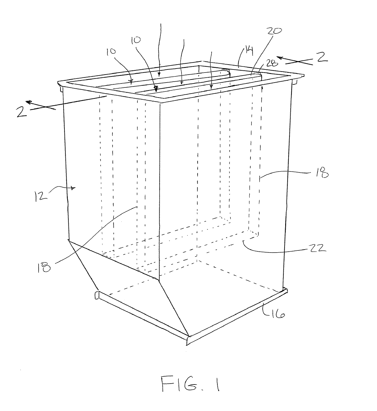
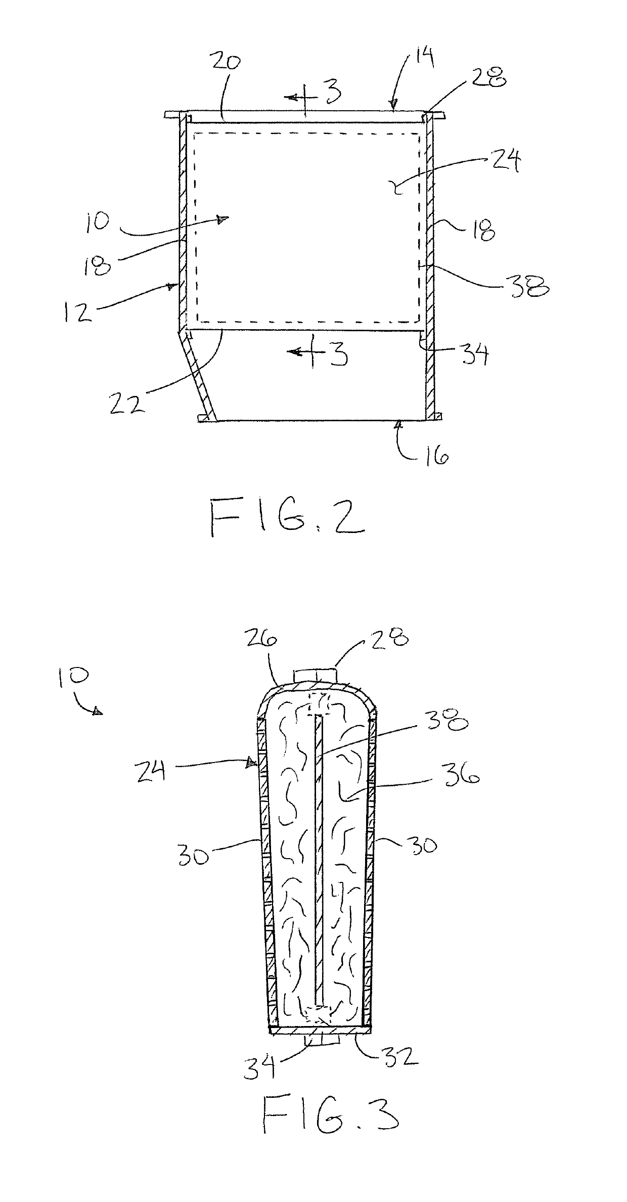
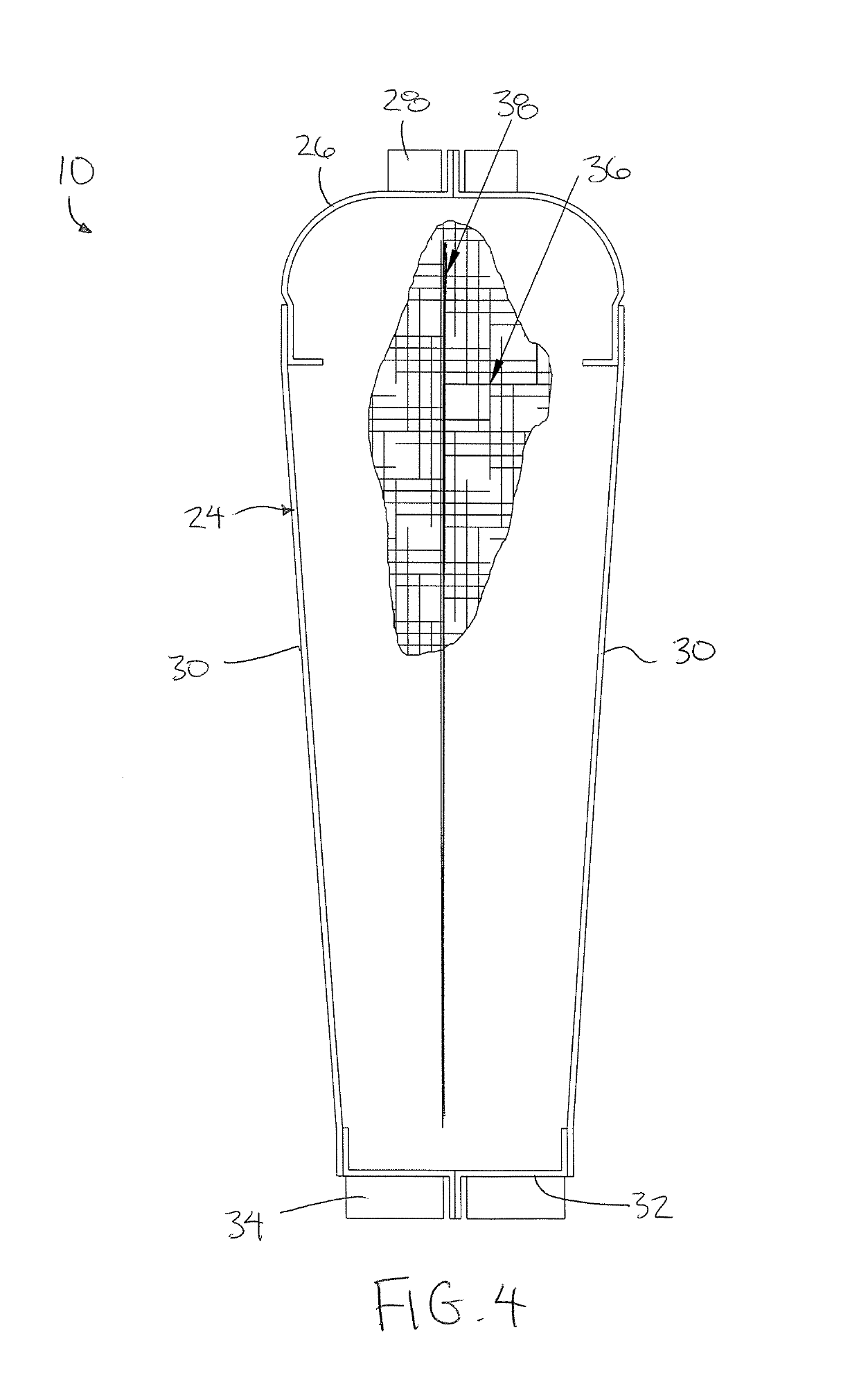
[0021]Referring to the accompanying figures there is illustrated a sound attenuating baffle device generally indicated by reference numeral 10. The device 10 is particularly suited for use in a silencer apparatus for attenuating sound in a ducted flow. The duct may be any suitable size or shape for receiving a flow of air or gas therethrough in a flow direction of the duct in air distribution HVAC systems, ventilation systems and other air movement systems for either air and gas streams

[0022]In the illustrated embodiment, the duct is a transitional duct section 12 having a rectangular cross-section which tapers to be reduced in cross-sectional area from an inlet end 14 to an outlet end 16. In further embodiments however, the sound attenuating baffle device 10 can be readily applied to any other type of duct including a straight duct section, or an elbow duct section while still achieving the benefits described herein. The flow direction through the duct is understood herein to corre...


PUM


Abstract

A sound attenuating baffle mounts within the duct section of an air distribution HVAC system, a ventilation system, or other air movement system for either air or gas streams, in which the duct section can be mounted directly to a fan or incorporated into a transmission duct. The sound attenuating baffle is typically oriented in the flow direction through the duct, and includes an outer casing containing sound absorbing material therein. An internal mass layer formed of a sound barrier material is suspended within the sound absorbing material which fills the outer casing. The mass layer increases the low frequency sound attenuation of the sound attenuating baffle.

Description

[0001]This application claims the benefit under 35 U.S.C. 119(e) of U.S. provisional application Ser. No. 62 / 299,331, filed Feb. 24, 2016.FIELD OF THE INVENTION[0002]The present invention relates to a sound attenuating baffle intended to be mounted within the duct of an air distribution HVAC system, a ventilation system, mounted directly to a fan or other air movement system for either air or gas streams in which the baffle is typically oriented in the flow direction through the duct. More particularly the present invention relates to a sound attenuating baffle of the type including an outer casing containing sound absorbing material therein and which is further provided with an internal mass layer formed of a sound barrier material suspended within the sound absorbing material, held in place with the outer casing.BACKGROUND[0003]Silencers are used in air distribution HVAC systems, ventilation systems and other air movement systems for either air and gas streams. Silencers typically...

Claims


Application Information

Patent Timeline
Patent Type & Authority Patents(United States)
IPC IPC(8): F24F13/24G10K11/168G10K11/04F24F13/00G10K11/16F24F13/02
CPCF24F13/24G10K11/04G10K11/168G10K11/161F24F13/02F24F2013/242
Inventor MOURATIDIS, EMANUEL
Owner VAW SYST LTD
Why Eureka
Try Eureka