Image processing apparatus, method, and program

a technology of image processing and apparatus, applied in the field of image processing methods, can solve the problems of image quality degradation, inability to completely eliminate overshooting or undershooting adjacent to an edge, etc., and achieve the effect of high quality

Inactive Publication Date: 2009-11-12
FUJIFILM CORP
View PDF6 Cites 6 Cited by
  • Summary
  • Abstract
  • Description
  • Claims
  • Application Information

AI Technical Summary

Benefits of technology

[0040]In this way, according to the first image processing apparatus and method, substantially the same gain is calculated for pixels in each of the one or more regions of the processing target image in which each pixel of the processing target image is included. Consequently, dynamic range compression of the processing target image does not cause overshooting and undershooting arising from a large pixel value variation adjacent to the boundary of the one or more regions in which each pixel of the image is included. Therefore, a high quality processed image without overshooting and undershooting may be obtained.
[0043]Here, the first and second low frequency images are close to each other in frequency band, so that the difference in blur degree is small. Therefore, the pixel level variation range in the first low frequency image becomes small at the boundary between the regions in which each pixel of the second low frequency image is included, so that the gains for the second low frequency image may be calculated appropriately.
[0045]Consequently, even where the frequency band of the low frequency image is low, by gradually increasing the gain to be calculated and frequency band for region splitting, the gain according to a global brightness variation of the processing target image may be calculated without being influenced by the variation range of pixel levels at the boundary between the regions in which each pixel of the processing target image is included. Accordingly, a high quality processed image without overshooting and undershooting may be obtained.

Problems solved by technology

In the dynamic range compression method described above, however, artifacts, such as overshooting, undershooting, and the like occur adjacent to an edge on an image, which cause a problem of image quality degradation.
The method described in Patent Document 1, however, is not able to completely eliminate overshooting or undershooting adjacent to an edge included in an image, since the dynamic range compression is performed based on frequency separation of the image.

Method used


Image

  • Image processing apparatus, method, and program
  • Image processing apparatus, method, and program
  • Image processing apparatus, method, and program

Examples


first embodiment

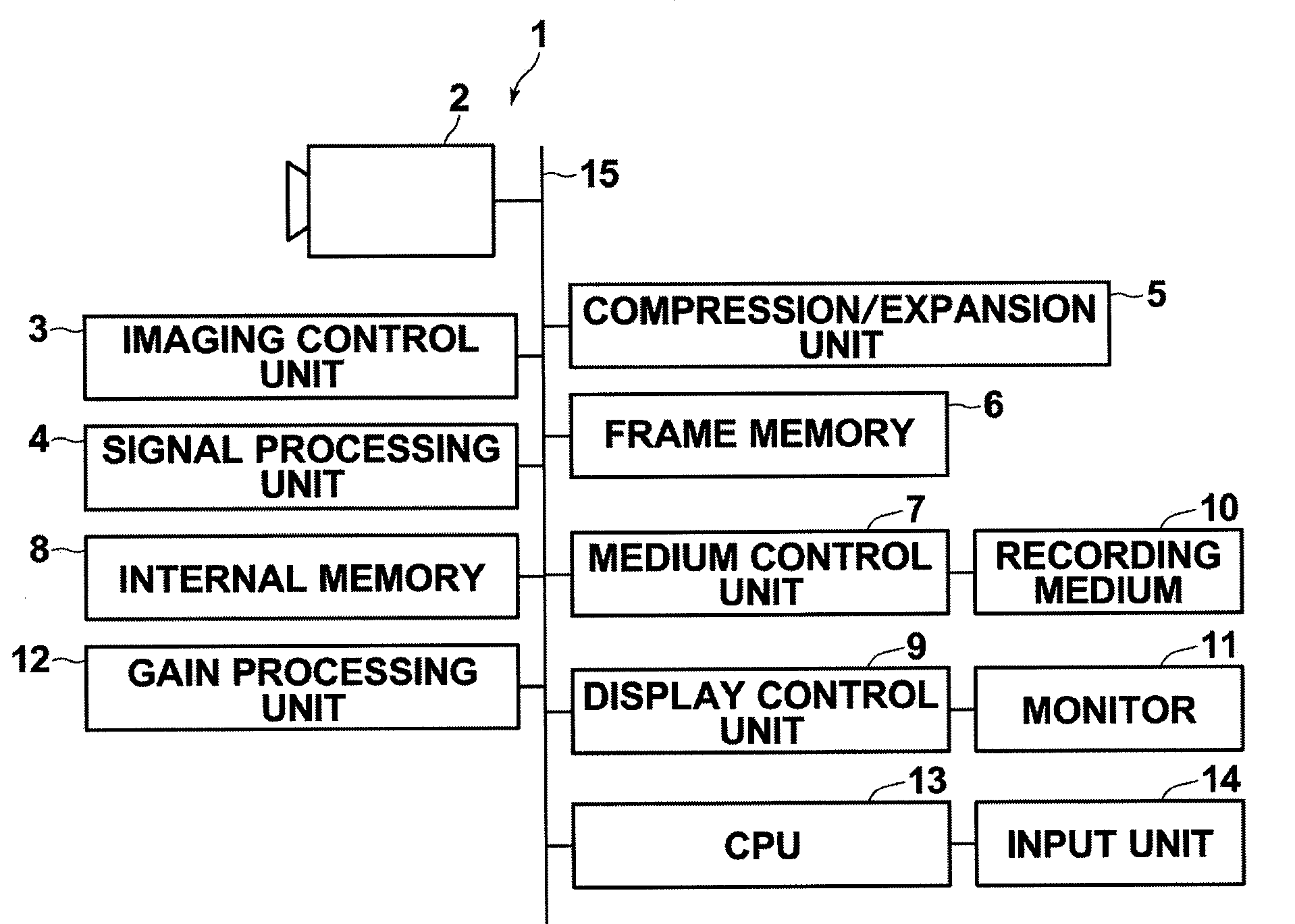
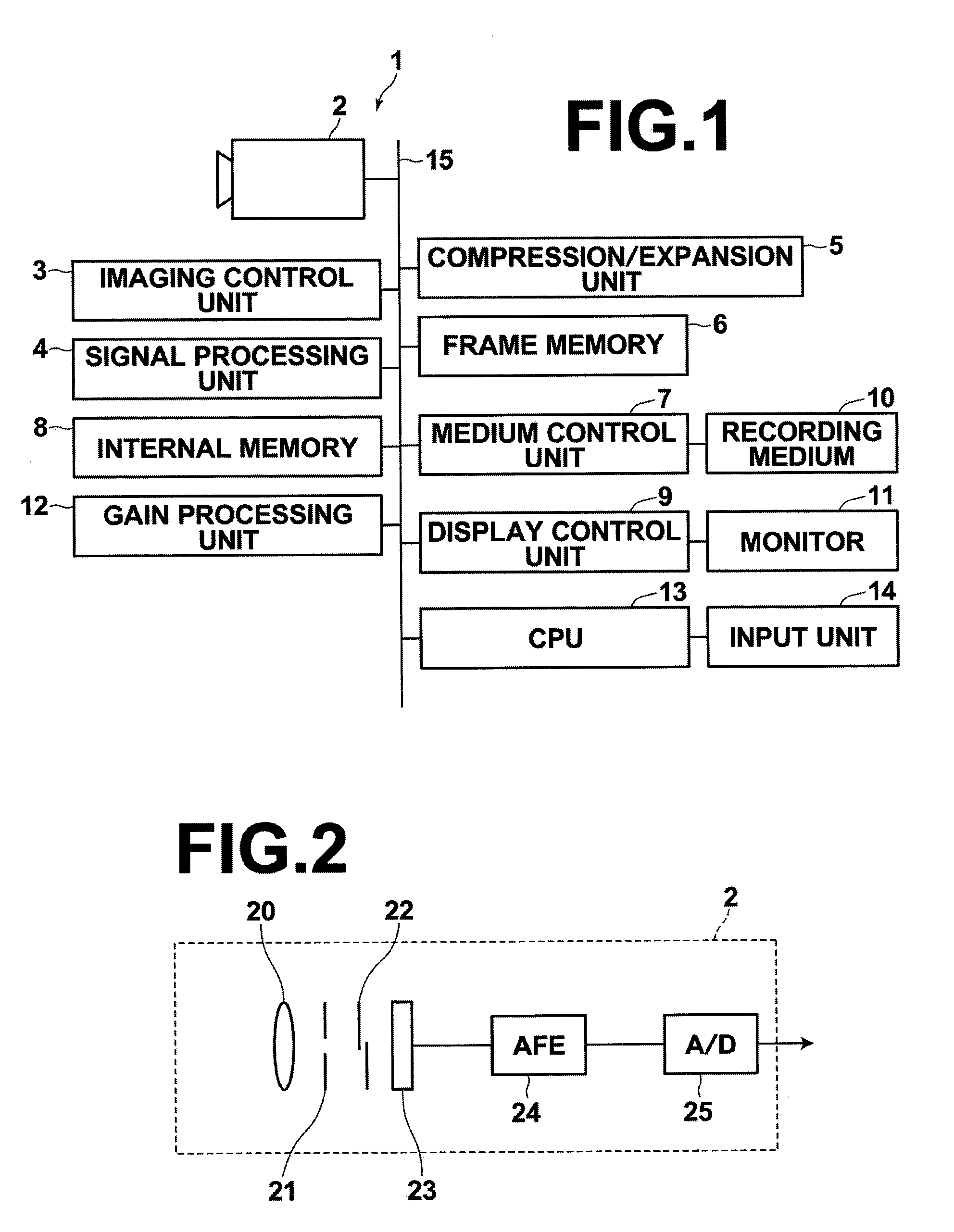
[0063]Hereinafter, embodiments of the present invention will be described with reference to the accompanying drawings. FIG. 1 is a schematic block diagram of a digital camera to which the image processing apparatus according to the present invention is applied, illustrating the configuration thereof. As illustrated in FIG. 1, digital camera 1 according to the present embodiment includes imaging unit 2, imaging control unit 3, signal processing unit 4, compression / expansion unit 5, frame memory 6, medium control unit 7, internal memory 8, and display control unit 9.

[0064]FIG. 2 illustrates a configuration of imaging unit 2. As illustrated in FIG. 2, imaging unit 2 includes lens 20, aperture 21, shutter 22, CCD 23, analog front-end (AFE) 24, and A / D converter 25.

[0065]Lens 20 includes a plurality of functional lenses, such as a focus lens for bringing a subject into focus, a zoom lens for realizing a zoom function and the like, and positions of the lenses are controlled by a not shown...

second embodiment

[0108] a plurality of blurred images Sus0 to Susn of different frequency bands is generated from image S0, and according to the level of each pixel of each of blurred images Sus1 to Susn having higher frequency bands than a lowest frequency band of the plurality of blurred images, one or more regions is set on each of blurred images Sus1 to Susn in which each pixel is included. Then, from provisional gains G0 calculated based on blurred image Sus0 having a lowest frequency band, provisional gains G1 is calculated based on the region setting result of blurred image Sus1, and thereafter the calculation is repeated until provisional gains Gn are calculated based on the region setting result of blurred image Susn having a highest frequency band.

[0109]Here, the frequency difference between blurred image Susi-1 and blurred image Susi is small because their frequency bands are close to each other. Therefore, the blurred range, i.e., variation range of pixel levels in blurred image Susi-1 b...


PUM


Abstract

An image processing apparatus, including a region setting unit for setting regions on a processing target image in which each pixel of the image is included according to a level of each pixel, a low frequency image generation unit for generating a low frequency image of the processing target image, a gain calculation unit for calculating a gain for each pixel of the processing target image such that the lower the level the greater the gain, wherein the unit calculates the gain such that pixels in each of the regions in which each pixel of the processing target image is included have substantially the same gain based on a region setting result and a level of each pixel of the low frequency image, and a processing unit for generating a processed image by performing dynamic range compression on the processing target image based on the gain.

Description

BACKGROUND OF THE INVENTION[0001]1. Field of the Invention[0002]The present invention relates to an image processing method and apparatus for compressing the dynamic range of an image by changing the gain of the image. The invention also relates to a computer readable recording medium on which is recorded a program for causing a computer to perform the image processing method.[0003]2. Description of the Related Art[0004]Reproduction of images after performing appropriate image processing is common practice in various fields. For example, a dynamic range compression method is proposed. The method generates a low frequency image of an image and reduces the contrast of a high luminance region, a low luminance region, or the entire image such that the difference between the maximum luminance value and minimum luminance value, i.e., dynamic range is reduced using the low frequency image. More specifically, a low frequency image of an image is generated, then a gain is calculated from the...

Claims


Application Information

Patent Timeline
Patent Type & Authority Applications(United States)
IPC IPC(8): H04N5/235G06T5/00H04N1/407H04N5/232H04N101/00
CPCG06T5/007G06T2207/20148G06T2207/20016G06T7/136
Inventor TANAKA, SEIJI
Owner FUJIFILM CORP
Why Eureka
Try Eureka