
Accommodating intraocular lens assembly

a technology for accommodating intraocular lenses and lenses, which is applied in the direction of intraocular lenses, eye implants, etc., and can solve problems such as significant limitations in all directions

Active Publication Date: 2019-04-23
DUDEE JITANDER +1
View PDF52 Cites 0 Cited by
  • Summary
  • Abstract
  • Description
  • Claims
  • Application Information

AI Technical Summary

Benefits of technology

The patent describes an accommodating intraocular lens assembly that can be implanted in an eye to treat presbyopia. The assembly includes a positive power lens and multiple stanchions that extend between a base end and a distal end. The assembly can be designed to move the positive power lens in response to the contraction of the assembly's arcuate periphery, which is connected to the base end. The assembly can also include a ring member and arcuate linking members that connect the distal ends of the stanchions. The assembly can be positioned in the eye by implanting it through a small incision and can provide improved vision and aesthetics compared to traditional intraocular lens implants.

Problems solved by technology

Several designs have been proposed in the prior art for AIOLS that attempt to achieve the variable focus distance of the youthful natural lens but all have significant limitations.

Method used


Image

  • Accommodating intraocular lens assembly
  • Accommodating intraocular lens assembly
  • Accommodating intraocular lens assembly

Examples


Embodiment Construction

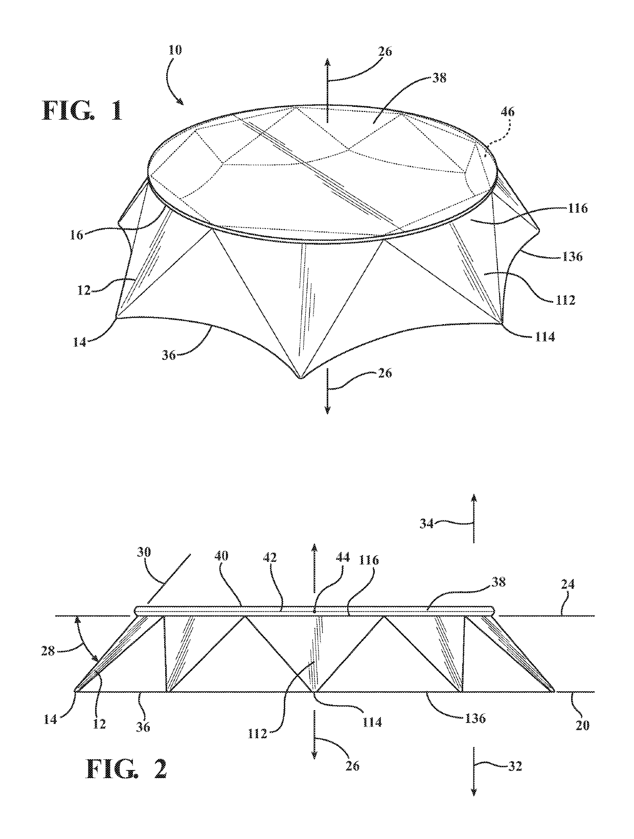
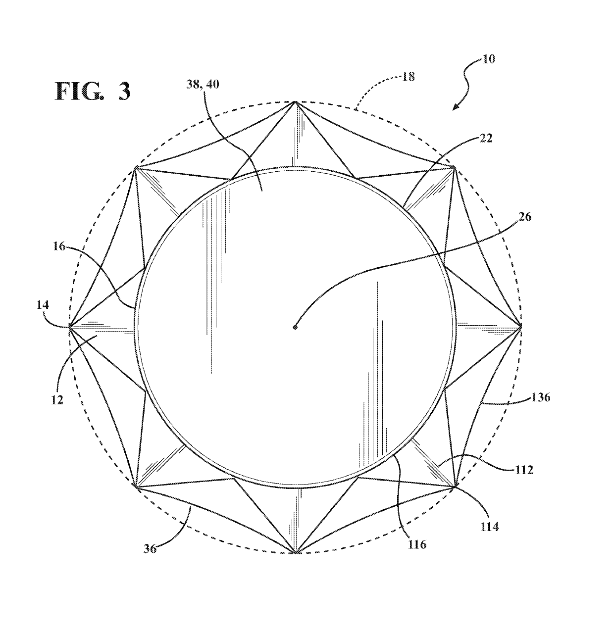
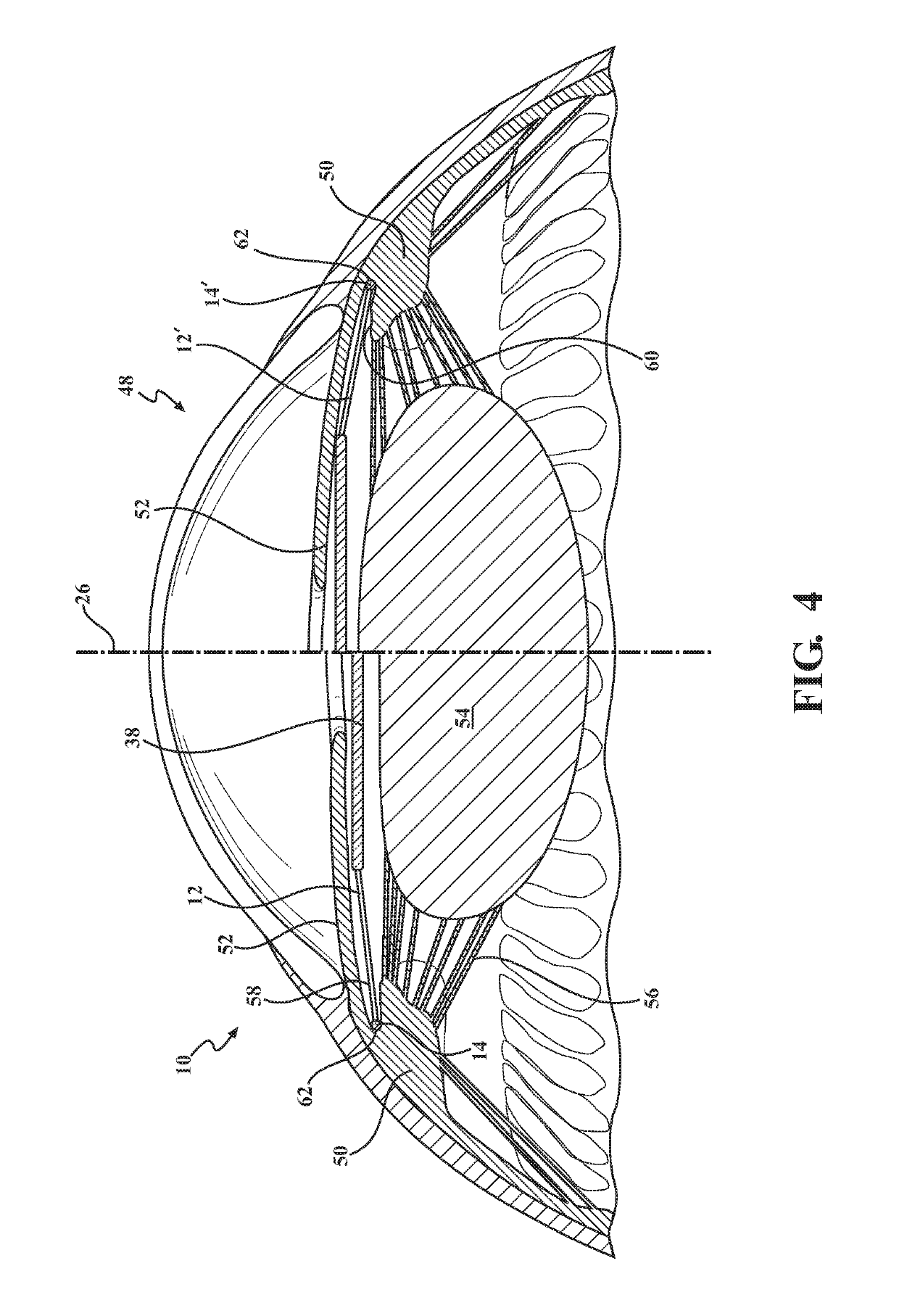
[0046]A plurality of different embodiments of the present disclosure is shown in the Figures of the application. Similar features are shown in the various embodiments of the present disclosure. Similar features across different embodiments have been numbered with a common reference numeral and have been differentiated by an alphabetic suffix. Similar features in a particular embodiment have been numbered with a common two-digit, base reference numeral and have been differentiated by a different leading numeral. Also, to enhance consistency, the structures in any particular drawing share the same alphabetic suffix even if a particular feature is shown in less than all embodiments. Similar features are structured similarly, operate similarly, and / or have the same function unless otherwise indicated by the drawings or this specification. Furthermore, particular features of one embodiment can replace corresponding features in another embodiment or can supplement other embodiments unless...


PUM


Abstract

A method of positioning an accommodating intraocular lens assembly in an eye can include implanting an accommodating intraocular lens assembly having a positive power lens in the eye. The accommodating intraocular lens assembly can also include a plurality of stanchions extending between base ends and distal ends. The base ends can be disposed in spaced relation to one another about a first arcuate periphery positioned in a ciliary sulcus of the eye. The distal ends can be disposed about a second arcuate periphery extending in a second plane positioned forward and outside of a capsular bag of the eye. The positive-power lens can be connected with the plurality of distal ends whereby a center of the positive power lens is moved along the central optic axis in response to contraction of the first arcuate periphery by contraction of the ciliary sulcus.

Description

CROSS-REFERENCE TO RELATED APPLICATIONS[0001]This application claims the benefit of U.S. Provisional Patent Application Ser. No. 62 / 097,052 for a POST SURGERY MODIFIABLE DYNAMICALLY ACCOMMODATING INTRA-OCULAR LENS IMPLANT, filed on 27 Dec. 2014, which is hereby incorporated by reference in its entirety.BACKGROUND[0002]1. Field[0003]The present disclosure relates to structures positionable in a human eye such as intraocular lens arrangements, drug delivery systems, sensor holders, and glaucoma treatment devices.[0004]2. Description of Related Prior Art[0005]Prosthetic intra-ocular lenses (IOLs) are routinely implanted following cataract extraction in human eyes and have grown in sophistication in order to provide better functional visual acuity with fewer troublesome distortions, reflections and aberrations to images focused on the retina. However, the natural lens retains distinct advantages over currently available IOLs. One such quality is the ability to alter its optical power to...

Claims


Application Information

Patent Timeline
Patent Type & Authority Patents(United States)
IPC IPC(8): A61F2/16
CPCA61F2/1632A61F2/161A61F2/1602A61F2/1608A61F2/16015A61F2/1629A61F2/1648A61F2002/1682A61F2002/1683
Inventor DUDEE, JITANDERDUDEE, SERENA HELEN
Owner DUDEE JITANDER
Learn More