Locomotion device on castors

a technology of locomotion and castors, which is applied in the direction of roller skates, skate boards, skating, etc., can solve the problems of difficult control of friction over the small contact area between the pad and the ball, and achieve the effect of preventing the skidding of the castors on braking and being easy to regula

Inactive Publication Date: 2019-04-30
COMMISSARIAT A LENERGIE ATOMIQUE ET AUX ENERGIES ALTERNATIVES
View PDF17 Cites 0 Cited by
  • Summary
  • Abstract
  • Description
  • Claims
  • Application Information

AI Technical Summary

Benefits of technology

[0017]The claimed device has the same advantages as that from US205. In fact, the fact that the castor can pivot about the rotation axis makes it possible to limit or even to prevent skidding of the castor on braking. Moreover, the fact that the braking torque exerted is a function of the amplitude of the turn angle also makes it possible to approximate the behavior of an ice skate, snowboard or ski.
[0018]Finally, in the claimed locomotion device, the amplitude of the braking torque depends primarily on the control of braking established by the central unit as a function of a measured physical parameter representing the turn angle. Thus it is much easier to regulate and to adjust the relationship between the amplitude of the braking torque and the turn angle.

Problems solved by technology

Under these conditions, it is difficult to control friction over the small area of contact between the pad and the ball.

Method used


Image

  • Locomotion device on castors
  • Locomotion device on castors
  • Locomotion device on castors

Examples


Embodiment Construction

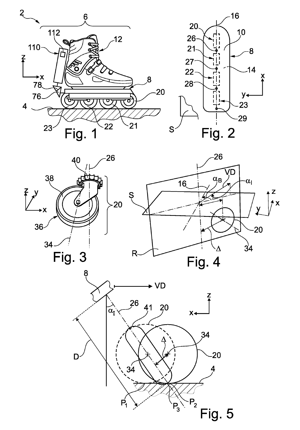
[0042]FIG. 1 shows part of a locomotion device 2. The device 2 enables a human being, referred to hereinafter as the user, to move by rolling over the ground 4. Here the surface of the ground 4 is plane and extends in a horizontal plane termed the ground plane. The device 2 is sufficiently light to be directly transported by hand by its user. For example, the device 2 weighs less than 25 kg or less than 15 kg and preferably less than 10 kg. Its overall size is also limited. For example. Its volume is less than 50 cm3. In this embodiment, the device 2 has no propulsion means, i.e. no thermal or electric motor able to propel the device 2 and its user over the ground 4.

[0043]By way of illustration, the device 2 is described in the particular case where it consists of two roller skates. Each of the skates is intended to be worn on a respective foot of the user. To simplify FIG. 1 and the subsequent figures, only the right skate 6 is shown. The left skate of the device 2 is deduced from ...


PUM


Abstract

A locomotion device on castors including: at least one castor mechanically connected to a sole to roll along a ground, the castor being mounted to rotate about an axis of rolling parallel to a plane of the sole and also about an axis of rotation perpendicular to the plane of the sole; a controllable electromechanical braking device configured to apply a braking torque to the castor that varies according to a braking command received; an inertial unit configured to measure a physical parameter indicative of a steering angle; and a central processing unit programmed to establish the braking command according to the physical parameter measured by the inertial unit and to transmit the established braking command to the braking device to apply to the castor a braking torque that varies according to the steering angle.

Description

FIELD[0001]The invention concerns a locomotion device on castors for moving over the ground.[0002]Numerous locomotion devices on castors are known such as, for example, roller skates. However, braking with roller skates or any other similar locomotion device, such as skateboards or roller skis, requires great dexterity and necessitates numerous hours of practice before being perfectly mastered. In fact, to achieve this, it is often necessary to cause the castors to skid along the ground.DESCRIPTION OF THE RELATED ART[0003]Various improvements have already been imagined for remedying this drawback. For example, the application US2002153205, hereinafter denoted US205, describes a locomotion device and more particularly roller skates. Each roller skate includes:[0004]a footplate extending primarily in a plane termed the “footplate plane” and on which at least one of the feet of the user is intended to be placed when the device is being used by that user,[0005]at least one castor mechan...

Claims


Application Information

Patent Timeline
Patent Type & Authority Patents(United States)
IPC IPC(8): A63C17/06A63C17/14
CPCA63C17/064A63C17/1427A63C2203/18
Inventor HILT, THIERRY
Owner COMMISSARIAT A LENERGIE ATOMIQUE ET AUX ENERGIES ALTERNATIVES
Why Eureka
Try Eureka