
Liquid ejecting apparatus and liquid ejecting method

a liquid ejecting apparatus and liquid ejecting technology, applied in the direction of matrix printers, visual presentations, instruments, etc., can solve the problems of image quality degradation, easy to see unevenness of images, etc., and achieve the effect of improving image quality and reducing contrast unevenness of images

Active Publication Date: 2019-04-30
SEIKO EPSON CORP
View PDF14 Cites 0 Cited by
  • Summary
  • Abstract
  • Description
  • Claims
  • Application Information

AI Technical Summary

Benefits of technology

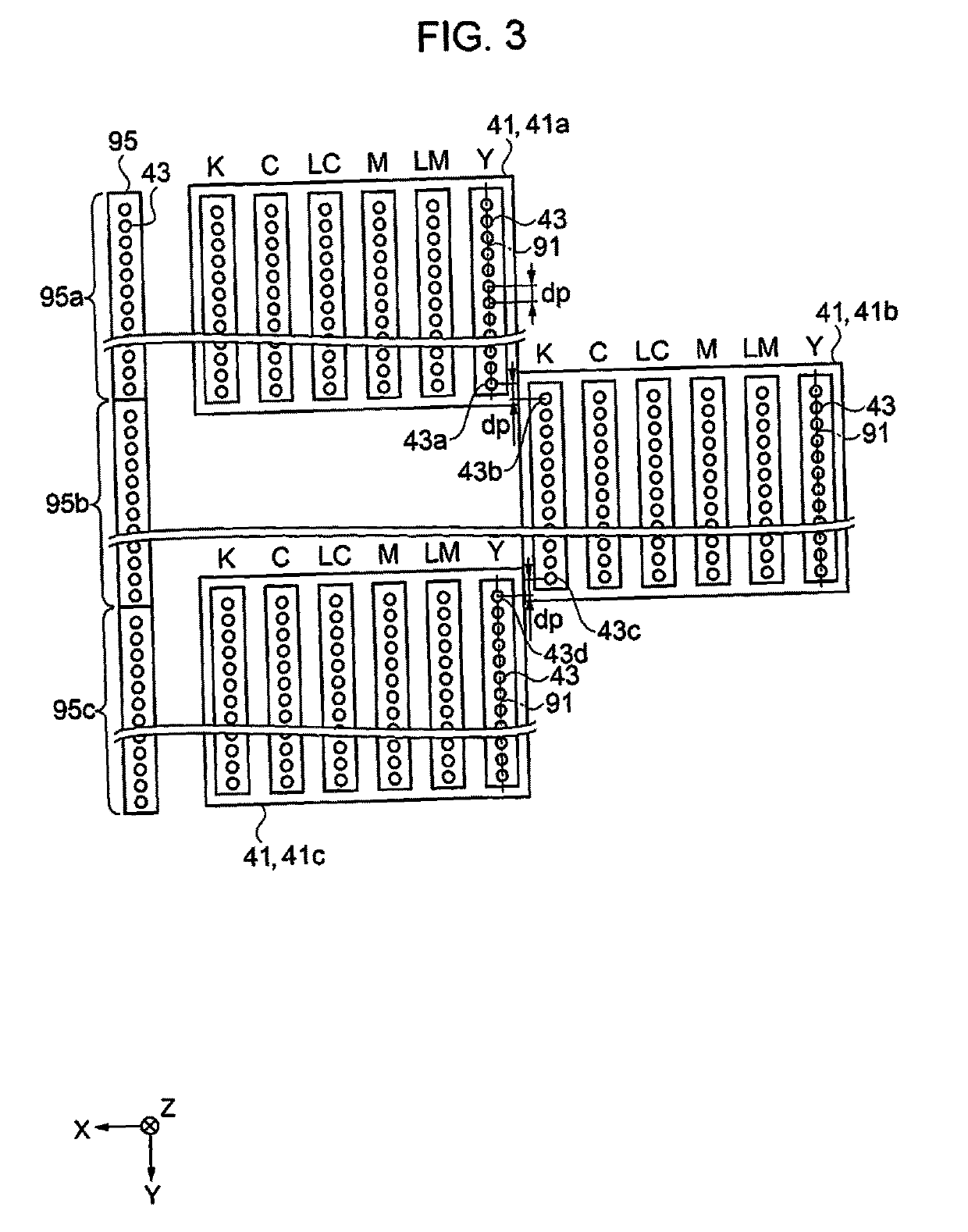
[0008]According to the configuration, since the total value of the nozzle usage rate of the first nozzle group corresponding to the respective raster lines formed is fixed, contrast in a plane of an image formed in the first nozzle group is uniform. Since the total value of the nozzle usage rate of the second nozzle group corresponding to the respective raster lines formed is fixed, contrast in a plane of an image formed in the second nozzle group is uniform. Since the total value of the nozzle usage rate of the third nozzle group corresponding to the respective raster lines formed is fixed, contrast in a plane of an image formed in the third nozzle group is uniform. Thereby, since the image formed by using the first nozzle group, the second nozzle group, and the third nozzle group is formed by combination of the image in which in-plane contrast is uniformized, contrast unevenness of the entire image is reduced. Thereby, it is possible to improve the image quality. The nozzle usage rate refers to a ratio of the number of liquid droplets (liquid) ejected from one nozzle in a scanning in the main scanning direction of one time of a total number of dots configuring the raster line.Application Example 2
[0010]According to the configuration, since the nozzle usage rate of the first nozzle group, the nozzle usage rate of the second nozzle group, and the nozzle usage rate of the third nozzle group are identical to each other in the respective raster lines, it is possible to further improve the image quality.Application Example 3
[0012]According to the configuration, by suppressing the nozzle usage rate of the end nozzle, it is possible to improve the ejection stability.Application Example 4
[0014]According to the configuration, it is possible to further improve the ejection stability.Application Example 5
[0016]According to the configuration, the contrast unevenness of the image can be reduced, and productivity can be improved.Application Example 6
[0018]According to the configuration, since the total value of the nozzle usage rate of the first nozzle group corresponding to the respective raster lines formed is fixed, contrast in a plane of an image formed in the first nozzle group is uniform. Since the total value of the nozzle usage rate of the second nozzle group corresponding to the respective raster lines formed is fixed, contrast in a plane of an image formed in the second nozzle group is uniform. Since the total value of the nozzle usage rate of the third nozzle group corresponding to the respective raster lines formed is fixed, contrast in a plane of an image formed in the third nozzle group is uniform. Thereby, since the image formed by using the first nozzle group, the second nozzle group, and the third nozzle group is formed by combination of the image in which in-plane contrast is uniformized, contrast unevenness of the entire image is reduced. Thereby, it is possible to improve the image quality.

Problems solved by technology

However, since the above apparatus has a deviation in a usage ratio of nozzles corresponding to the first nozzle column and the second nozzle column, there is a problem that a contrast unevenness of an image is easily visible, and an image quality is degraded.

Method used


Image

  • Liquid ejecting apparatus and liquid ejecting method
  • Liquid ejecting apparatus and liquid ejecting method
  • Liquid ejecting apparatus and liquid ejecting method

Examples


first embodiment

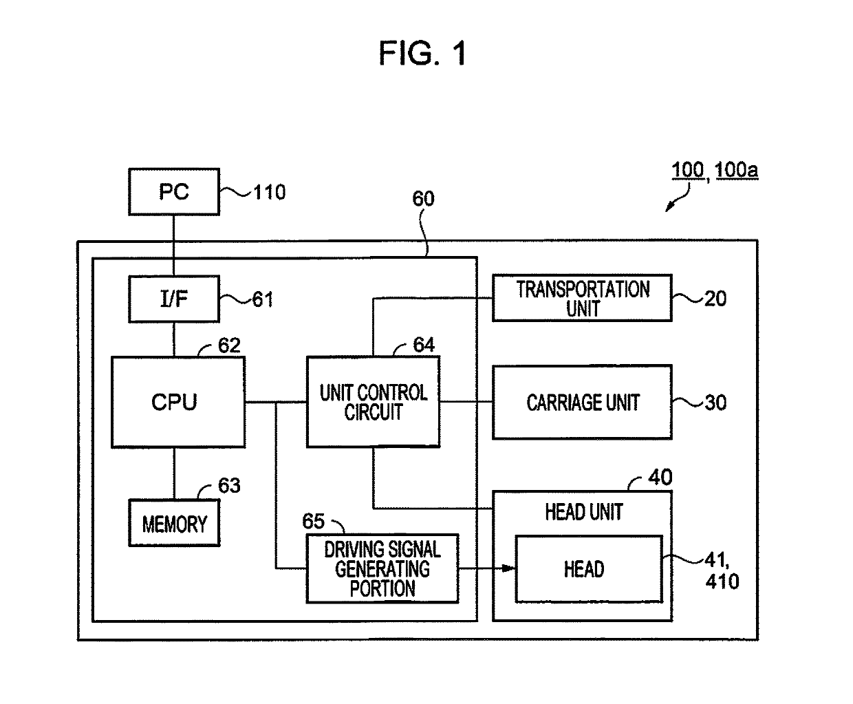
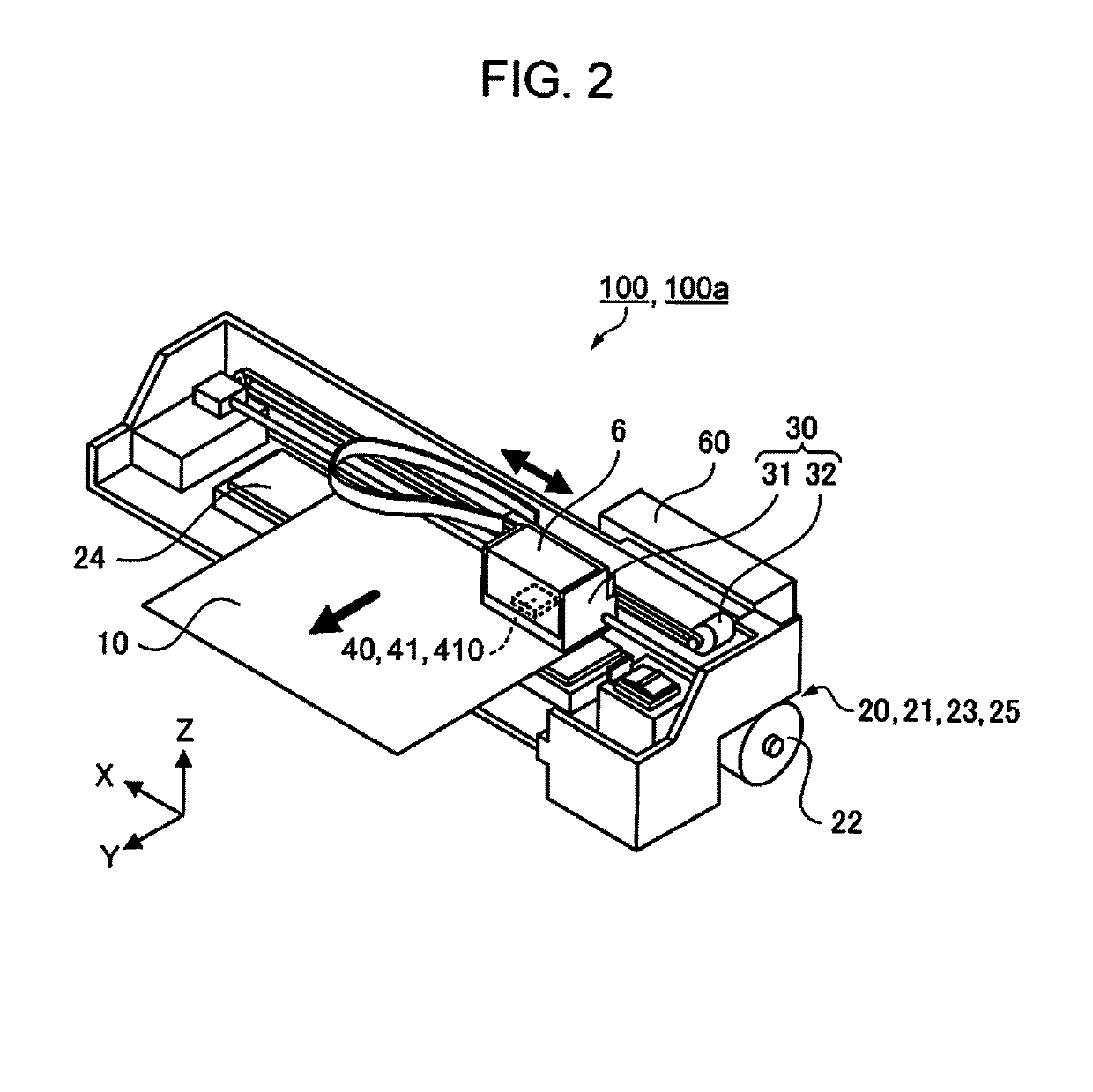
[0041]First, a configuration of a liquid ejecting apparatus will be described. FIG. 1 is a block diagram illustrating the configuration of the liquid ejecting apparatus, and FIG. 2 is a perspective view illustrating the configuration of the liquid ejecting apparatus. The liquid ejecting apparatus is provided with a head having a plurality of nozzles capable of ejecting liquid on a medium, a main scanning unit that scans the head in a main scanning direction, a sub scanning unit that relatively moves between the head and the medium in a sub scanning direction intersecting the main scanning direction, and a control unit. The liquid ejecting apparatus, for example, is an ink jet printer having a serial method. Hereinafter, a specific configuration of the liquid ejecting apparatus will be described.

[0042]The liquid ejecting apparatus 100 includes a transporting unit 20 as the sub scanning unit, a carriage unit 30 as the main scanning unit, a head unit 40, and a control unit 60. The liqu...

second embodiment

[0107]Next, a second embodiment will be described. Since a basic configuration of a liquid ejecting apparatus 100a of the embodiment is the same as the configuration of the liquid ejecting apparatus 100 of the first embodiment, a description of the basic configuration will be omitted (refer to FIGS. 1 and 2). Hereinafter, the configuration different from the first embodiment will be described. Specifically, although the first embodiment has the configuration provided with three heads 41, the configuration further provided with a fourth nozzle group having a plurality of the nozzles, that is, provided with four heads will be described in the embodiment.

[0108]First, a configuration of a head will be described. FIG. 12 is an explanatory view illustrating an example of the configuration of the head. As illustrated in FIG. 12, the apparatus is configured of four heads 410 (first head 410a, second head 410b, third head 410c, and fourth head 410d). Nozzle columns 910 are provided for each ...

modification example 1

[0184]Although the first and second embodiment described above have a configuration provided with a plurality of the heads 41 (410), these are not limited thereto. For example, the head may be one. In this case, for the nozzle columns configuring a plurality of nozzles disposed in one head, the first nozzle group and the second nozzle group may be configured. That is, it may be configured to be provide with a plurality of nozzle groups, and to form the respective raster lines with the path number of equal to or greater than the number of the nozzle group. Even in this case, it is possible to obtain the same effect described-above.


PUM


Abstract

A liquid ejecting apparatus includes a head in which a first nozzle group, a second nozzle group, and a third nozzle group which have a plurality of nozzles are disposed in a predetermined direction, and that can eject a liquid on a medium, a main scanning unit that scans the head in a main scanning direction, a sub scanning unit that relatively moves between the head and the medium in a sub scanning direction intersecting the main scanning direction; and a control unit. When the liquid is ejected to form a plurality of raster lines on the medium, the control unit maintains fixed values for each total value of a nozzle usage rate of the first nozzle group, total value of a nozzle usage rate of the second nozzle group, and total value of a nozzle usage rate of the third nozzle group, corresponding to the respective raster lines.

Description

BACKGROUND[0001]1. Technical Field[0002]The present invention relates to a liquid ejecting apparatus and a liquid ejecting method.[0003]2. Related Art[0004]In the related art, by alternately repeating a transportation operation that transports a medium in a transportation direction, and a dot forming operation that ejects liquid from a first nozzle and a second nozzle, while moving a first nozzle column in which a plurality of first nozzles are arranged in the transportation direction and a second nozzle column in which a plurality of second nozzles are arranged in the transportation direction in a movement direction to form a dot on the medium, a liquid ejecting apparatus that forms a plurality of dot columns configured of the dot arranged in the movement direction in the transportation direction is known (for example, refer to JP-A-2009-137247).[0005]However, since the above apparatus has a deviation in a usage ratio of nozzles corresponding to the first nozzle column and the seco...

Claims


Application Information

Patent Timeline
Patent Type & Authority Patents(United States)
IPC IPC(8): B41J2/045G06K15/10B41J2/21B41J2/205B41J2/145
CPCG06K15/105B41J2/04581B41J2/2132B41J2/2054B41J2/145B41J2/07
Inventor YOSHIKAWA, EISHIN
Owner SEIKO EPSON CORP
Learn More