Power connector

Active Publication Date: 2019-04-30
AVERTRONICS
View PDF30 Cites 5 Cited by
  • Summary
  • Abstract
  • Description
  • Claims
  • Application Information

AI Technical Summary

Benefits of technology

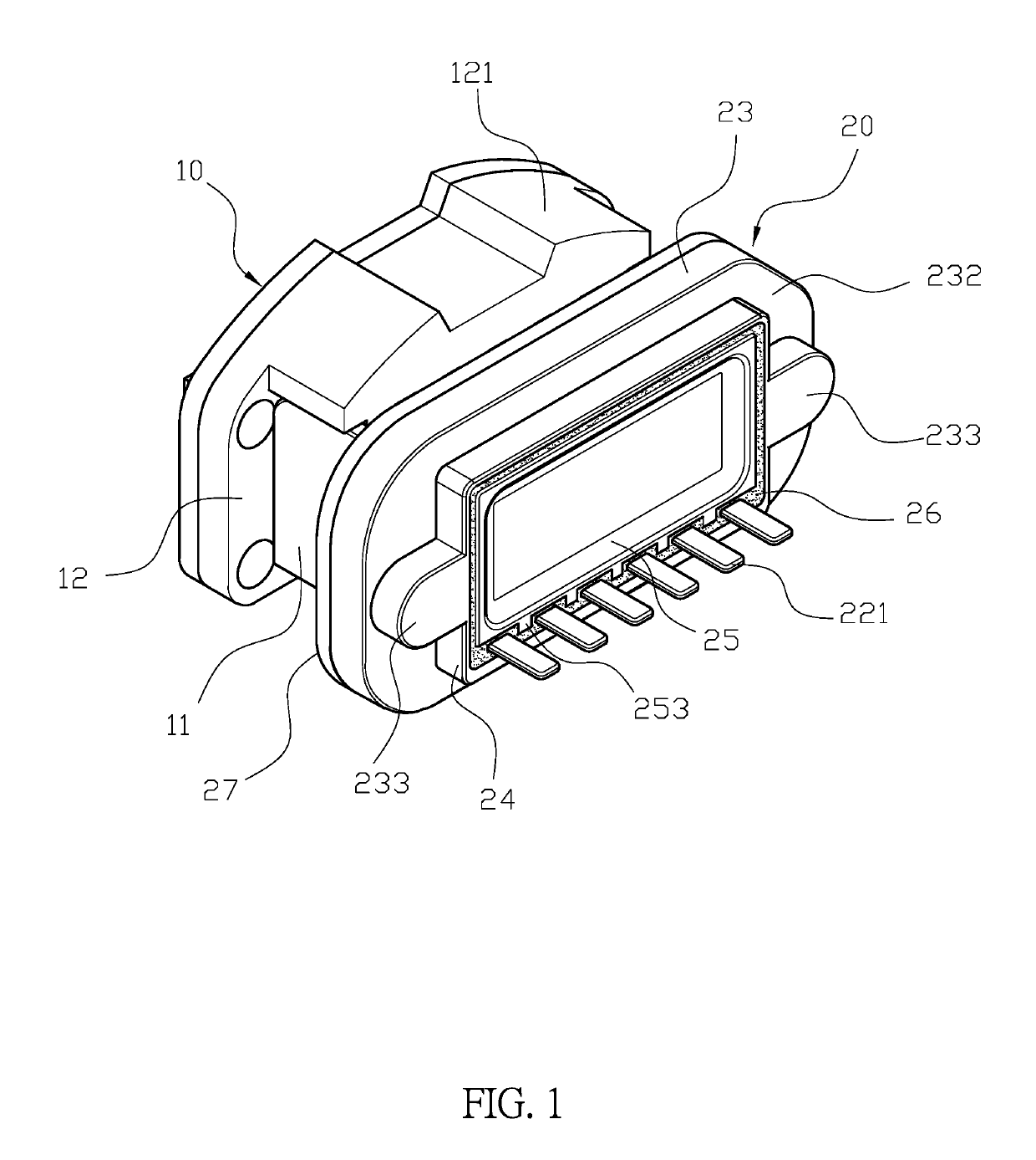
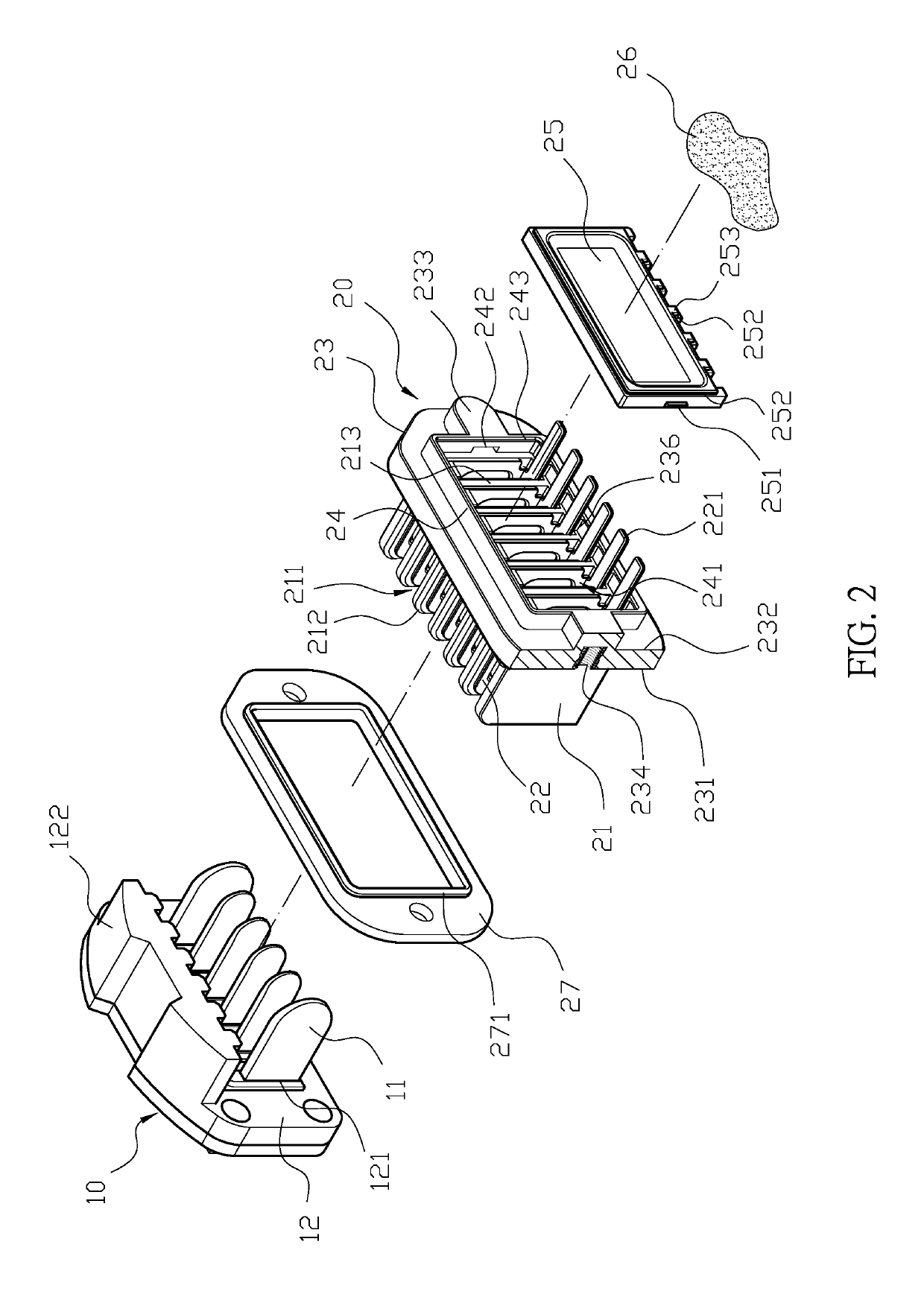
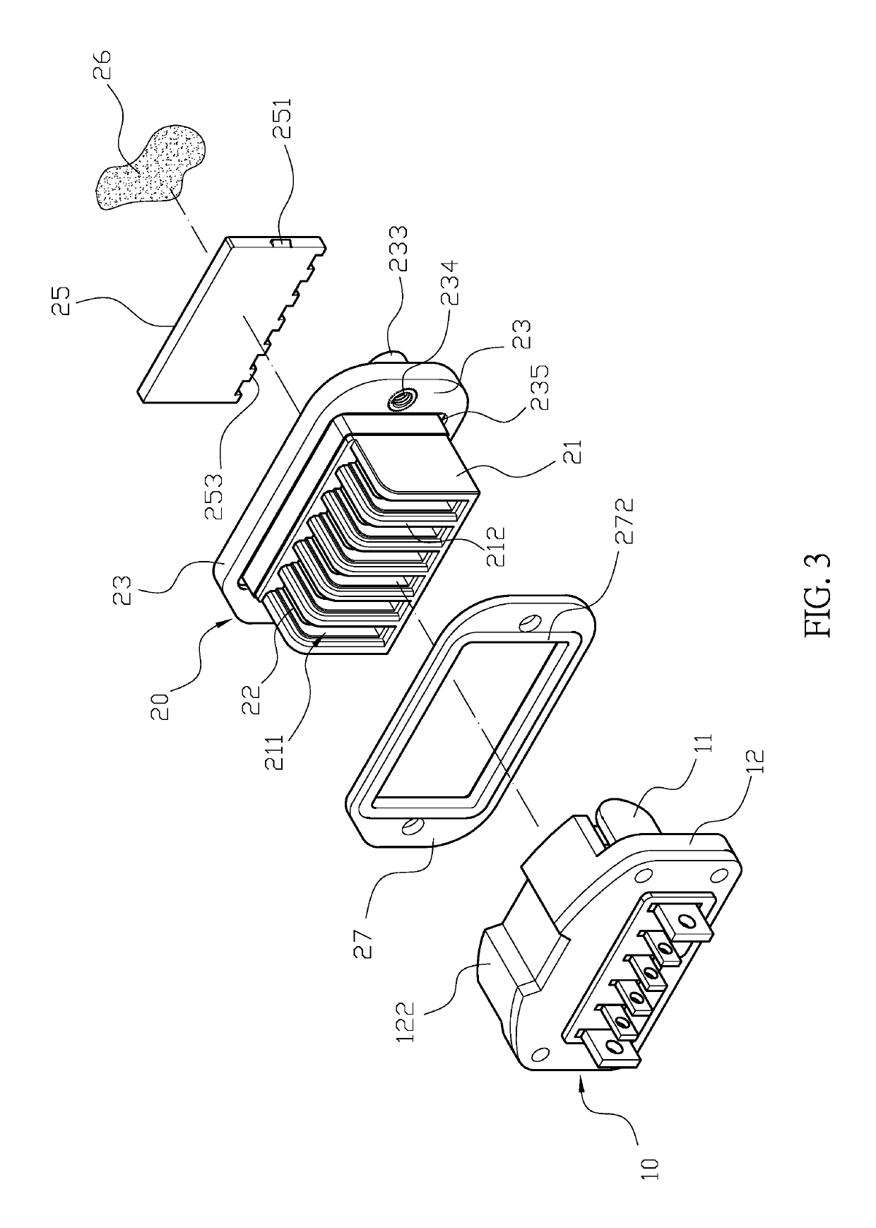
[0014]Comparing with conventional power connector, the present invention is advantageous because: (i) the cover is disposed in the first housing, and the engaging blocks are respectively engaged with the engaging slots such that the cover is filled with the first housing, and the engagement between the engaging block and the engaging slot is configured to secure the relative position of the second frame and the cover so as to enforce the structural strength of the assembly; (ii) the hot-melt adhesive layer is configured to fill along a way between the second frame and the cover so as to

Problems solved by technology

Nevertheless, the connector is a part which has whole circuit and is relatively prone to get breakdown due to humidity.
However, the conventional power connector is disadvantageous because: the pressures caused by force point and non-force point are usually different when the outer cover is locked, which results that gasket is not evenly clamped be

Method used


Image

  • Power connector
  • Power connector
  • Power connector

Examples


Embodiment Construction

[0026]The detailed description set forth below is intended as a description of the presently exemplary device provided in accordance with aspects of the present invention and is not intended to represent the only forms in which the present invention may be prepared or utilized. It is to be understood, rather, that the same or equivalent functions and components may be accomplished by different embodiments that are also intended to be encompassed within the spirit and scope of the invention.

[0027]Unless defined otherwise, all technical and scientific terms used herein have the same meaning as commonly understood to one of ordinary skill in the art to which this invention belongs. Although any methods, devices and materials similar or equivalent to those described can be used in the practice or testing of the invention, the exemplary methods, devices and materials are now described.

[0028]All publications mentioned are incorporated by reference for the purpose of describing and disclos...


PUM


Abstract

A power connector may comprise a first connecting member and a second connecting member. The first connecting member has a plurality of first terminals, and a connecting base formed at an end of the second connecting member comprises a plurality of L-shaped slots thereon, and each of the L-shaped slots has a second terminal secured therein. When the first terminals and the second terminals are connected, the first connecting member and the second connecting member are electrically connected. The other end of the second connecting member has a first base which comprises a connecting surface and an assembling surface, and a second frame protruding from the assembling surface has a first housing therein. A cover is disposed in the first housing, and an outer periphery of the cover has a first packing groove filled with a hot-melt adhesive layer to achieve sealing effect.

Description

FIELD OF THE INVENTION[0001]The present invention relates to a power connector and more particularly to a blade-typed power connector.BACKGROUND OF THE INVENTION[0002]Generally, it is common that an electronic device connects to a power supply or other circuits through a wire having a male connector and a female connector at two ends thereof, and through quick connection of the male and female connectors, the electronic device can be electrically connected to a power supply. Nevertheless, the connector is a part which has whole circuit and is relatively prone to get breakdown due to humidity. Also, many electronic devices are used in outdoor or the environment which is humid or where temperature varies greatly, or even in the electronic equipment in motion, and the power connector used for these kinds of electronic devices have a high requirement for waterproof function and electrical connection stability. Thus, a waterproof power connector has been developed, which usually comprise...

Claims


Application Information

Patent Timeline
IPC IPC(8): H01R13/52H01R13/11
CPCH01R13/5219H01R13/113H01R13/521H01R13/4367H01R13/512H01R13/5216
Inventor LAI, AUSTINLAI, CHI-ICHANG, CHUNG JEN
Owner AVERTRONICS
Why Eureka
Try Eureka