Air valve connecting device for different inflation valves

a technology of air valves and connecting devices, which is applied in the direction of machines/engines, mechanical equipment, positive displacement liquid engines, etc., can solve the problems of increasing manufacturing costs and manufacturing procedures, and achieve the effects of convenient operation, simple or improved structure, and convenient connection

Active Publication Date: 2019-05-07
BETO ENG & MARKETING
View PDF13 Cites 3 Cited by
  • Summary
  • Abstract
  • Description
  • Claims
  • Application Information

AI Technical Summary

Benefits of technology

[0008]The primary objective of the present invention is to provide an air valve connecting device including a simplified or improved structure for easily connecting to different inflation valves and for being easily actuated or operated with a single hand of the user and for being easily manufactured with a decreased manufacturing procedure and cost.
[0014]A clamping ring is engaged between the barrel and the housing for positioning the barrel to the housing and for preventing the barrel from being disengaged from the housing. The first end portion of the shank is connected to a hose for receiving the pressurized air from the hose. A shield is engaged onto the hose and the first end portion of the shank for clamping and securing the hose to the shank and for preventing the hose from being disengaged from the shank.

Problems solved by technology

However, normally, the typical air valve connecting heads required to be provided with an actuating handle or hand grip to be grasped or held or operated with one hand of the user, and the user has to use the other hand to grasp and actuate or operate the valve housing, such that the typical air valve connecting heads comprise a structure that may not be easily operated or may not effectively grasping or holding the different inflation valves and may comprise a greatly increased manufacturing cost and manufacturing procedures.

Method used


Image

  • Air valve connecting device for different inflation valves
  • Air valve connecting device for different inflation valves
  • Air valve connecting device for different inflation valves

Examples


Embodiment Construction

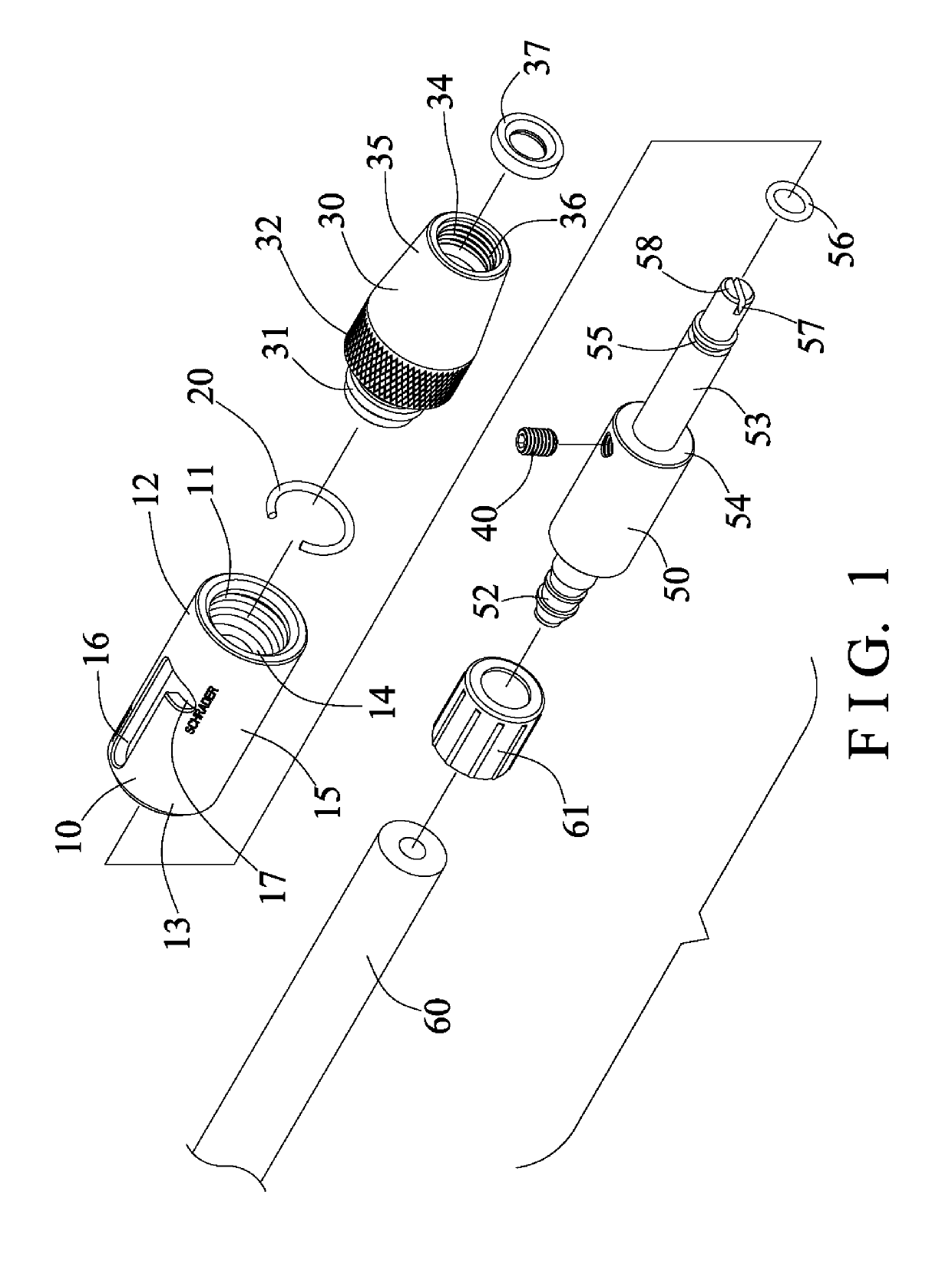
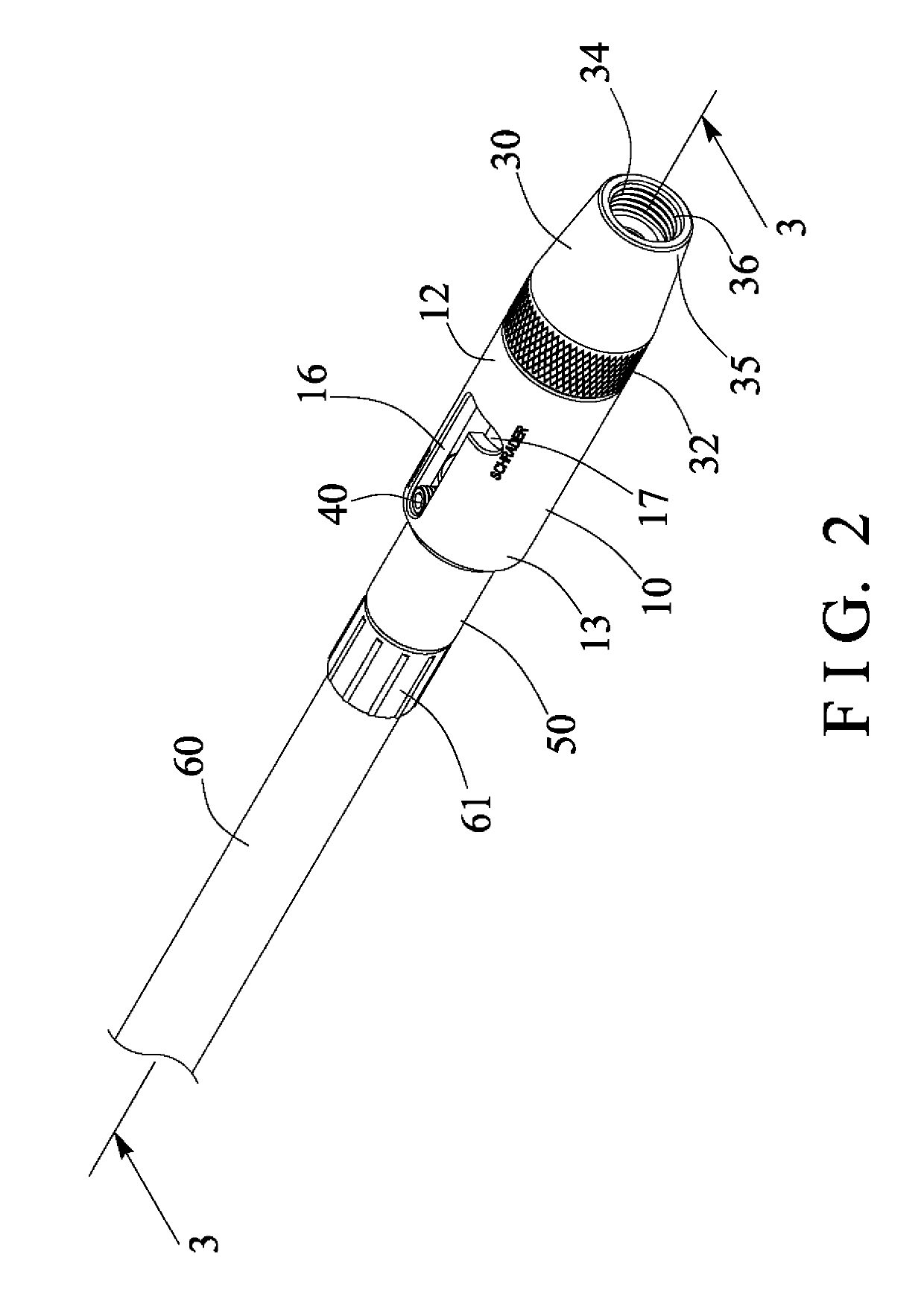
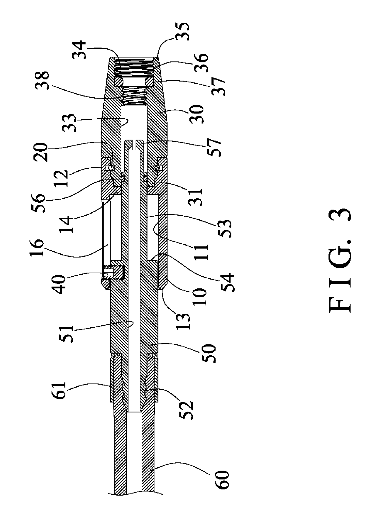
[0022]Referring to the drawings, and initially to FIGS. 1-3, an air valve connecting device in accordance with the present invention comprises a valve connecting body or housing 10 including a bore or chamber 11 formed therein, and including one or front or first end portion 12 and another or rear or second end portion 13, and a peripheral swelling or bulge 14 extended radially and inwardly therefrom, such as extended radially and inwardly into the chamber 11 at the middle or intermediate portion 15 of the housing 10. The housing 10 further includes a longitudinal slot 16 and a lateral slot 17 formed or provided therein and intersecting or communicating with each other and for forming or defining an L-shaped guiding or limiting slot 16, 17 therein, and also communicating with the chamber 11 of the housing 10.

[0023]A cylindrical tube or barrel 30 is pivotally or rotatably connected or coupled to the housing 10, for example, the barrel 30 includes one or front or first end portion 31 ...


PUM


Abstract

An air valve connecting device includes a barrel rotatably connected to a housing, the barrel includes an enlarged space having a screw hole for engaging with a U.S. type inflation valve, and having an inner thread for selectively engaging with a French type inflation valve and for detachably securing the French type inflation valve to the barrel, and a shank is slidably engaged in the housing and includes one end portion for receiving the pressurized air, and the shank includes a front end portion having a mouth movable toward the barrel for selectively engaging with either the U.S. type inflation valve or the French type inflation valve.

Description

BACKGROUND OF THE INVENTION[0001]1. Field of the Invention[0002]The present invention relates to an air valve connecting head or device, and more particularly to an air valve connecting device including a simplified or improved structure for easily connecting to different inflation valves and for being easily actuated or operated with a single hand of the user and for being easily manufactured with a decreased manufacturing procedure and cost.[0003]2. Description of the Prior Art[0004]Various kinds of typical air valve connecting devices have been developed and comprise a valve housing including one end for connecting or coupling to a pressurized air reservoir and for receiving the pressurized air from the pressurized air reservoir, and a fitting port formed in the other end of the valve housing for receiving or engaging with an inflation valve and for inflating the balls, the inner tires of the bicycles or the motorcycles or the vehicles, the present inventor has developed various ...

Claims


Application Information

Patent Timeline
Patent Type & Authority Patents(United States)
IPC IPC(8): F04B33/00F04B39/14F04B39/12F04B39/10F16K1/00
CPCF04B33/005F04B39/10F16K1/00F04B39/14F04B39/123
Inventor WANG, LO PIN
Owner BETO ENG & MARKETING
Why Eureka
Try Eureka