
Electronic track light

a track light and electronic technology, applied in the field of track lights, can solve the problems of only rotating in a single plane, unfavorable exterior, etc., and achieve the effect of good

Active Publication Date: 2019-05-21
DONGGUAN ZHAO HE LIGHTING CO LTD
View PDF10 Cites 15 Cited by
  • Summary
  • Abstract
  • Description
  • Claims
  • Application Information

AI Technical Summary

Benefits of technology

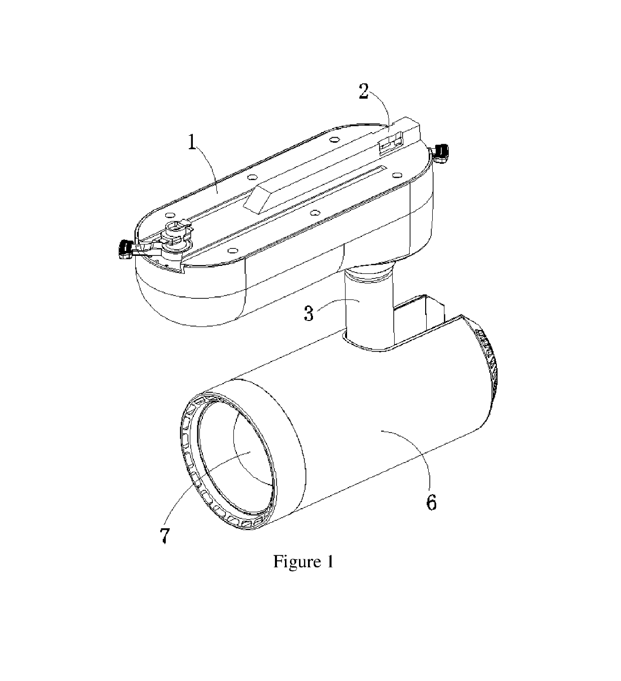
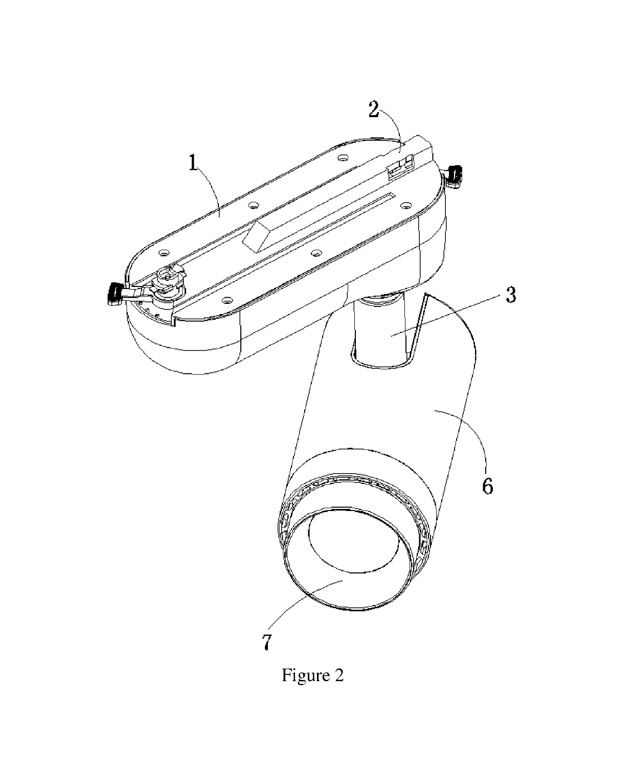
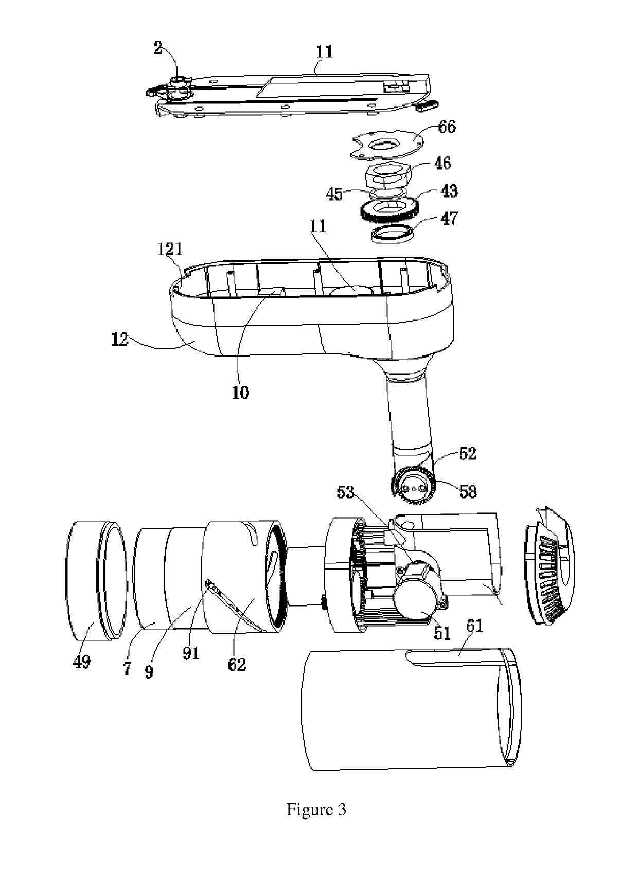
The innovation is an electronic track light system with zoomable optical units that can adjust the angle in three dimensions. The system includes a driving machinery that can adjust the lighting angle and a telescopic system that can adjust the beam angle degree. The control unit is located inside the track box, allowing the fixture to have a dimmable function. The colorful exterior provides good decoration effect.

Problems solved by technology

However, there are several disadvantages to the above electronic track light.
Second, this lighting only can rotate in single plane, cannot rotate in three dimensions.
Fourth, the exterior is not beautiful.

Method used


Image

  • Electronic track light
  • Electronic track light
  • Electronic track light

Examples


Embodiment Construction

[0029]In the following description, numerous specific details are set forth in order to provide a more thorough description of the present invention. It will be apparent, however, to one skilled in the art, that the present invention may be practiced without these specific details. In other instances, well-known features have not been described in detail so as not to obscure the invention.

[0030]The description for the attached figures are only for explanation and demonstration purposes and is not a limitation for this innovation. The following words in this application, namely, “center,”“vertical direction,”“horizontal direction,”“length,”“width,”“thickness,”“up,”“down,”“forward,”“back,”“left,”“right,”“vertical,”“horizontal,”“upper,”“bottom,”“inside,”“outside,”“clockwise,” and “anticlockwise” are directions or positions for the figures and these directions or positions are only for the purpose of description of this innovation, instead of a limitation of the innovation. Moreover, th...


PUM


Abstract

This innovation includes an electronic track light, including a track box, a rotation clip on the that connects the track box and a track, a pole at a side of the track box and a rotation system at the top of the pole connected to electronic driving machinery. The electronic driving machinery can drive the rotation system to rotate the pole around an axis. There is a swinging system at the bottom of the pole that connects the pole, fixture and the first driving machinery. The first driving machinery can drive the swinging system to different positions. There is a telescopic system in another side of the fixture and a second driving machinery that can drive the telescopic system to move a lens and front frame to different positions. A control unit links and controls the driving machinery and the first and second machineries.

Description

BACKGROUND OF THE INVENTION1. Cross-Reference to Related Application[0001]This application claims priority to China Patent Application No. 201810034014.3, filed Jan. 15, 2018.2. Field of the Invention[0002]The invention relates to track lights and in particular to an electronic track light.3. Related Art[0003]A track light is installed in the track. The track light can adjust the lighting angle according to the location of the object in order to show the best visual effect of the object; Normally, the applications of the track light are the store, exhibition, and museum.[0004]In current situation, the track light can adjust the lighting angle, but this adjustment needs to be through the manual operation.[0005]In order to solve above issue, the China Patent titled “electronic track light” (Patent No. 201610196850.2) shows a kind of electronic track light. This light uses driving machinery 1 to slide the whole track light system along a track. This light uses driving machinery 2 to ro...

Claims


Application Information

Patent Timeline
Patent Type & Authority Patents(United States)
IPC IPC(8): F21V21/15F21V21/28F21V21/34
CPCF21V21/15F21V21/34F21V21/28F21V14/06F21V21/30
Inventor SHIH, MING FENG
Owner DONGGUAN ZHAO HE LIGHTING CO LTD
Learn More