
Plug connector with damping element

a technology of damping element and plug connector, which is applied in the direction of coupling device connection, coupling base/case, two-part coupling device, etc., can solve the problems of affecting the service life of the plug connector, etc., and achieves the effect of moving the insulating par

Active Publication Date: 2019-05-28
ROSENBERGER HOCHFREQUENZTECHNIK GMBH & CO KG
View PDF28 Cites 5 Cited by
  • Summary
  • Abstract
  • Description
  • Claims
  • Application Information

AI Technical Summary

Benefits of technology

The present invention provides a plug connector that can transmit high currents with minimal wear and tear even under high mechanical stresses like vibrations. The plug connector includes an insulating part that keeps the inner conductor contact spaced apart from the outer conductor part. A resiliently compressible damping element is provided on the plug connector that reduces the movability of the insulating part relative to the inner conductor contact and / or relative to the outer conductor part when a complementary mating plug connector is plugged in. This results in a more durable high-current plug connector arrangement.

Problems solved by technology

However, it has been found that a plug connector structured in this way is susceptible to increased wear if it is subjected to high mechanical stresses.
For this reason, conventional high-current plug connectors generally require maintenance, and components affected by wear such as inner conductor contacts or insulating parts generally need to be replaced.

Method used


Image

  • Plug connector with damping element
  • Plug connector with damping element
  • Plug connector with damping element

Examples


second embodiment

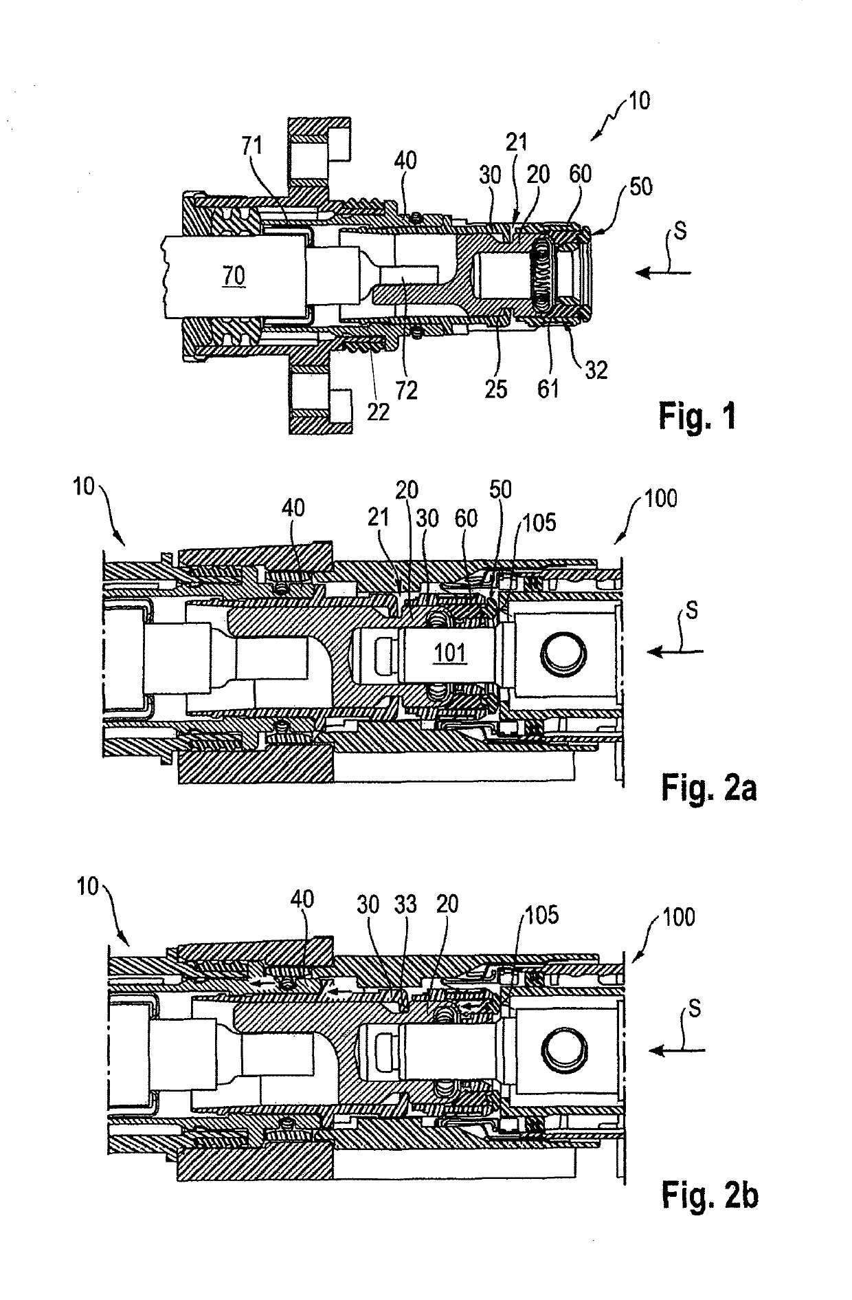
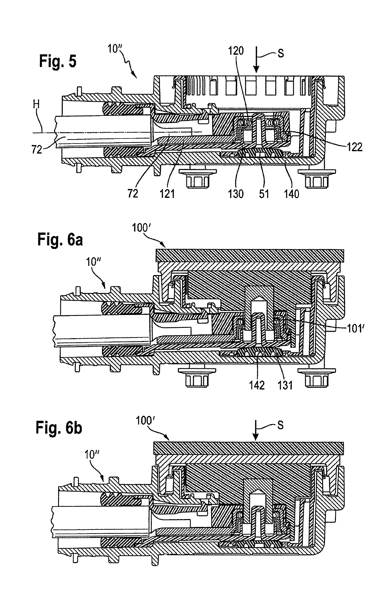
[0046]A second preferred embodiment of the invention is explained in the following. In this second embodiment, the resiliently compressible damping element is arranged between the insulating part and the outer conductor part. When the mating plug connector is plugged in, the insulating part is pressed in the direction of the outer conductor part, as a result of which the damping element is compressed in the insertion direction, and as a result the movability between the insulating part and the outer conductor part is restricted.

[0047]In terms of achieving an even application of pressure it has thereby proved expedient that the damping element has a substantially planar form and is arranged between a substantially flat contact surface of the outer conductor part and a counter pressure surface of the insulating part. In a sectional plane running transversely to the insertion direction, a substantially round contour of the damping element has proved particularly advantageous. A plug co...

first embodiment

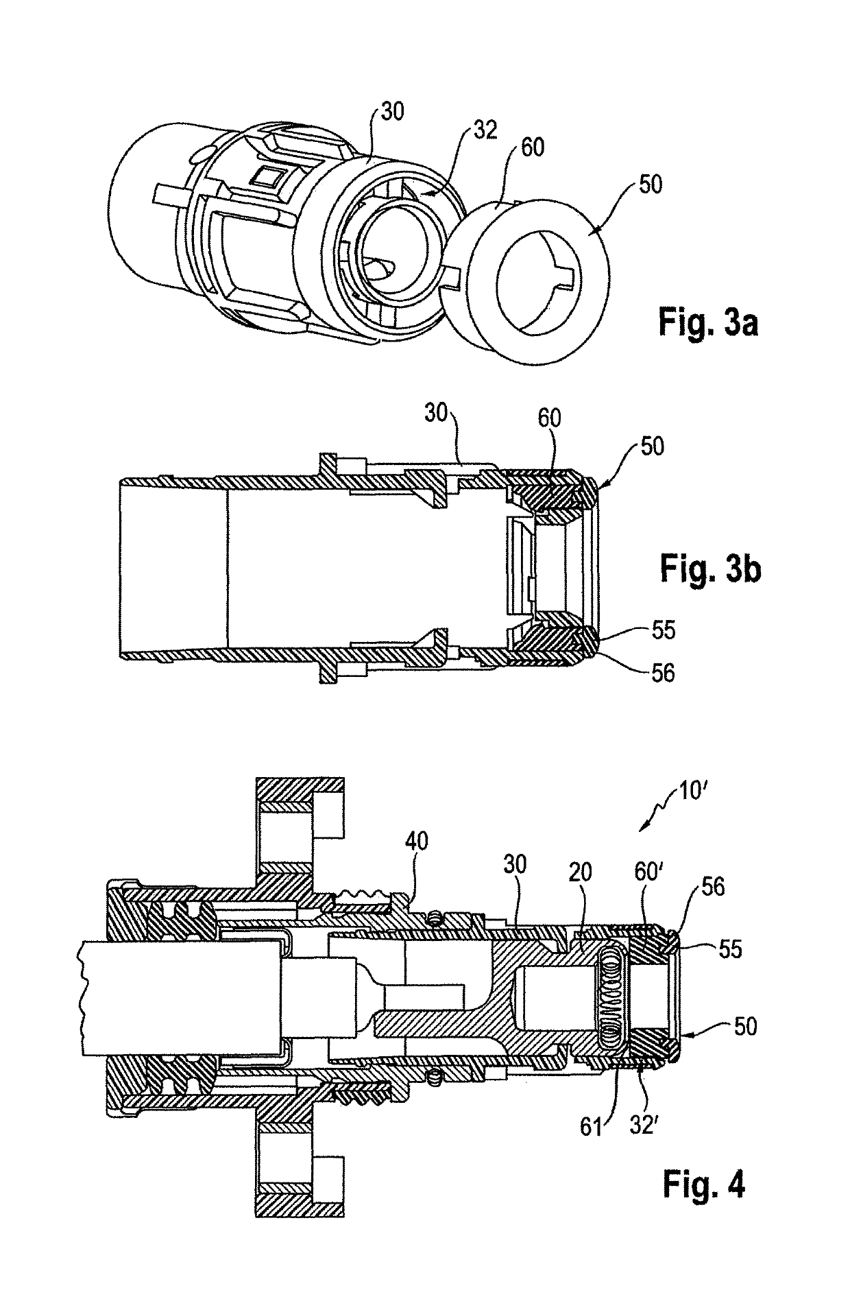
[0053]FIG. 1 shows a plug connector according to the invention 10 in a longitudinal sectional view. The plug connector 10 consists of an inner conductor contact 20 which is surrounded by an insulating part 30 made of a non-conductive material such as plastic. The insulating part 30 prevents the inner conductor contact 20 from coming into electrical contact with an outer conductor part 40 of the plug connector 10.

[0054]The plug connector 10 is connected with a coaxial cable 70, wherein the shielding 71 of the coaxial cable 70 is coupled electrically with the outer conductor part 40 of the plug connector and the inner conductor 72 of the coaxial cable 70 is coupled electrically with the inner conductor contact 20 of the plug connector 10, for example by soldering or crimping.

[0055]The inner conductor contact 20 is designed on the plug side as a socket with a contact spring into which a contact element 101 of a mating plug connector 100 in the form of a contact pin can be inserted in o...


PUM


Abstract

A high current connector, having an inner conductor contact for carrying current, an outer conductor part, and an isolator part which keeps the inner conductor contact spaced apart from the outer conductor part, wherein a resiliently compressible damping element is provided on the connector in such a way that, when a complementary counterpart connector is inserted into the connector, the element is resiliently compressible in an insertion direction and the mobility of the isolator part is reduced with respect to the inner conductor contact and / or with respect to the outer conductor part. This feature is used to eliminate play between the affected parts to lessen material wear.

Description

BACKGROUND OF THE INVENTION[0001]1. Field of the Invention[0002]The invention relates to a plug connector, in particular a high-current plug connector, comprising an inner conductor contact, an outer conductor part and an insulating part which keeps the inner conductor contact spaced apart from the outer conductor part.[0003]While the inner conductor contact is intended to carry current, the outer conductor part can be designed in the form of a housing, for example an outer conductor housing and / or can be earthed and thus shield the inner conductor. Such a coaxial plug connector can be coupled to a coaxial cable, wherein the outer conductor of the coaxial cable makes electrical contact with the outer conductor part of the plug connector and an inner conductor of the coaxial cable makes electrical contact with the inner conductor contact of the plug connector.[0004]2. Description of Related Art[0005]Plug connectors are used generally for the detachable connection of electrical cables...

Claims


Application Information

Patent Timeline
Patent Type & Authority Patents(United States)
IPC IPC(8): H01R9/05H01R13/53H01R13/502H01R24/38H01R103/00
CPCH01R13/53H01R24/38H01R13/5025H01R2103/00
Inventor ZEBHAUSER, MARTINPRASCHBERGER, NORBERTTEICHMANN, PAUL
Owner ROSENBERGER HOCHFREQUENZTECHNIK GMBH & CO KG
Learn More