
Permanent magnet rotor for synchronous electric motor

a permanent magnet and synchronous electric motor technology, applied in the direction of magnetic circuit rotating parts, dynamo-electric machines, magnetic circuit shape/form/construction, etc., can solve the problems of permanent magnets and difficult to reduce cogging force, and achieve the effect of reducing cogging force and demagnetization resistance capacity

Active Publication Date: 2019-06-04
FANUC LTD
View PDF16 Cites 4 Cited by
  • Summary
  • Abstract
  • Description
  • Claims
  • Application Information

AI Technical Summary

Benefits of technology

[0017]The present invention provides a permanent magnet rotor for a synchronous electric motor that can realize reducing a cogging force and restraining a reduction of a demagnetization resistant capacity at a permanent magnet end portion in a balanced manner.

Problems solved by technology

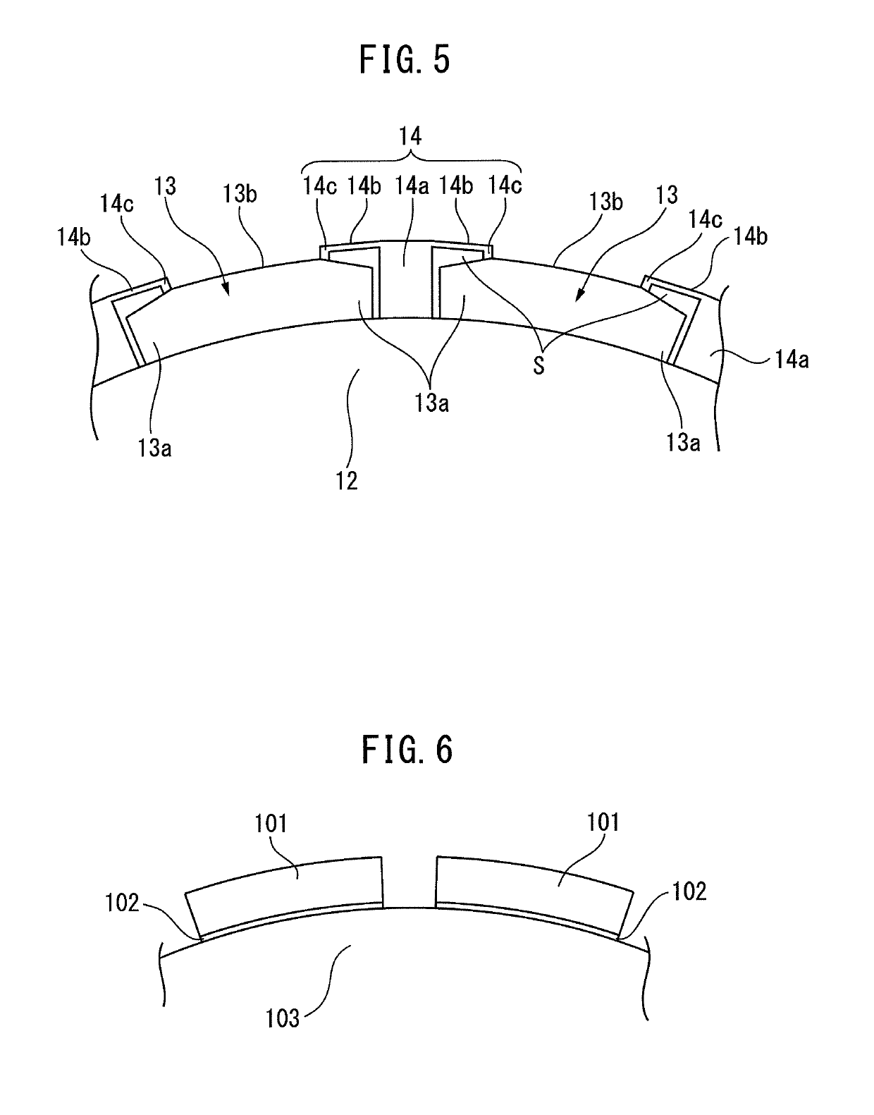
As a result, there occurs a problem in that, also when the same demagnetizing field is applied to the permanent magnets in the circumferential direction of the rotor core, the end portion of the permanent magnets is more apt to be demagnetized than the center portion of the permanent magnets.
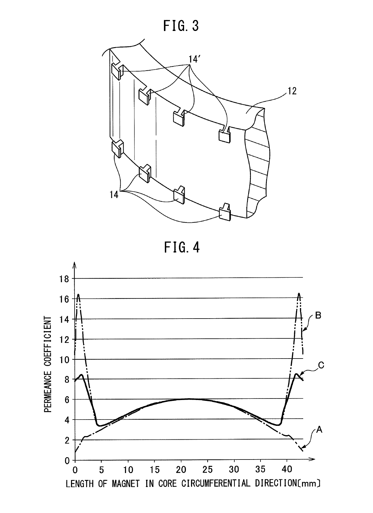
In addition, when the projection portions are configured to have a shape for tightly engaging with the end portion of the permanent magnets as described above, the permeance coefficient and the demagnetization resistant capacity of the end portion of the permanent magnets are remarkably increased, which accordingly makes it difficult to reduce the cogging force.

Method used


Image

  • Permanent magnet rotor for synchronous electric motor
  • Permanent magnet rotor for synchronous electric motor
  • Permanent magnet rotor for synchronous electric motor

Examples


Embodiment Construction

[0029]Next, embodiments of the present invention will be described with reference to the drawings. In the following figures, the same components will be assigned the same reference signs. In addition, it is assumed that the elements denoted by the same reference signs in different drawings denote elements having the same functions. Further, to facilitate understanding, these figures are suitably changed in scale.

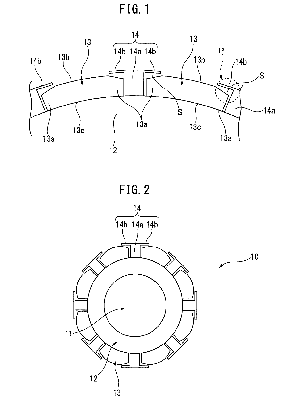
[0030]FIG. 1 is an enlarged diagram illustrating a cross-sectional structure of a part of a rotor according to an embodiment of the present invention. Further, FIG. 2 is a schematic diagram illustrating a cross-sectional structure of the entirety of the rotor according to the embodiment of the present invention. In particular, the diagrams are a view in which a permanent magnet fixing structure relative to a rotor core is seen from a direction along a rotation axis of the rotor.

[0031]With reference to FIGS. 1 and 2, a rotor 10 according to the present embodiment includes a c...


PUM


Abstract

Provided is a permanent magnet rotor that includes a plurality of magnets sequentially disposed on an outer circumferential surface of a core having a cylindrical shape along a circumferential direction of the core and a plurality of projection portions each disposed between the magnets adjacent to each other. Then a cover portion is formed such that a height of a space in a radial direction of the core is more reduced as from a base portion of the projection portions toward a tip end of the cover portion.

Description

BACKGROUND OF THE INVENTION[0001]1. Field of the Invention[0002]The present invention relates to a permanent magnet rotor (hereinafter, briefly referred to as rotor) for a synchronous electric motor.[0003]2. Description of the Related Art[0004]As a rotor of a synchronous electric motor, commonly, either a radial type rotor or a surface magnet type rotor is used. The radial type rotor is configured by sequentially disposing a rotor core forming a yoke and a permanent magnet in an alternate manner in a circumferential direction. On the other hand, the surface magnet type rotor is configured by sequentially sticking a plurality of permanent magnets on an outer circumferential surface of a cylindrical rotor core in a circumferential direction.[0005]On the permanent magnets of the rotor as described above, a centrifugal force following rotation of the rotor and a magnetic attraction force due to a magnetic field of a stator disposed around the rotor act at a radial direction outer side o...

Claims


Application Information

Patent Timeline
Patent Type & Authority Patents(United States)
IPC IPC(8): H02K1/28H02K1/27H02K29/03
CPCH02K1/28H02K1/278H02K29/03
Inventor NISHIFUKUMOTO, AKIRAMITSUI, HIDETOSHI
Owner FANUC LTD
Learn More