
Image capturing device and brightness adjusting method

a technology of image capturing and brightness adjustment, which is applied in the direction of color television details, television system details, television systems, etc., can solve the problems of inability to obtain the details of the object in the image, and the visibility of the background of the image is worse, so as to achieve effective improvement of image visibility

Active Publication Date: 2019-06-04
VIVOTEK INC
View PDF25 Cites 2 Cited by
  • Summary
  • Abstract
  • Description
  • Claims
  • Application Information

AI Technical Summary

Benefits of technology

The solution effectively balances brightness across the image, enhancing visibility by adjusting exposure parameters or light intensities based on calculated differences, thereby improving overall image quality.

Problems solved by technology

However, when an object is close to the camera, the object located in the foreground of the image may be overexposed, such that the details of the object in the image cannot be obtained.
However, the aforesaid manner will make the visibility of the background of the image worse.

Method used


Image

  • Image capturing device and brightness adjusting method
  • Image capturing device and brightness adjusting method
  • Image capturing device and brightness adjusting method

Examples


Embodiment Construction

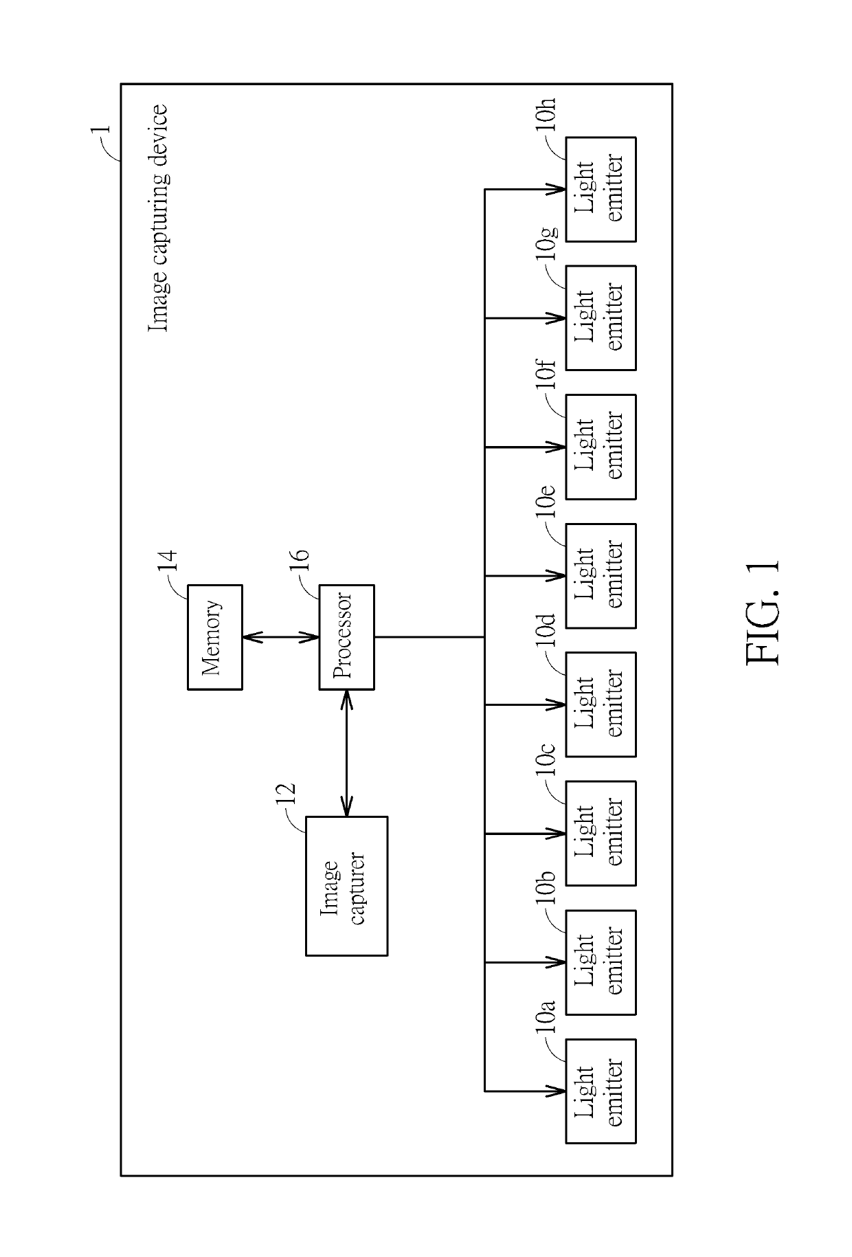
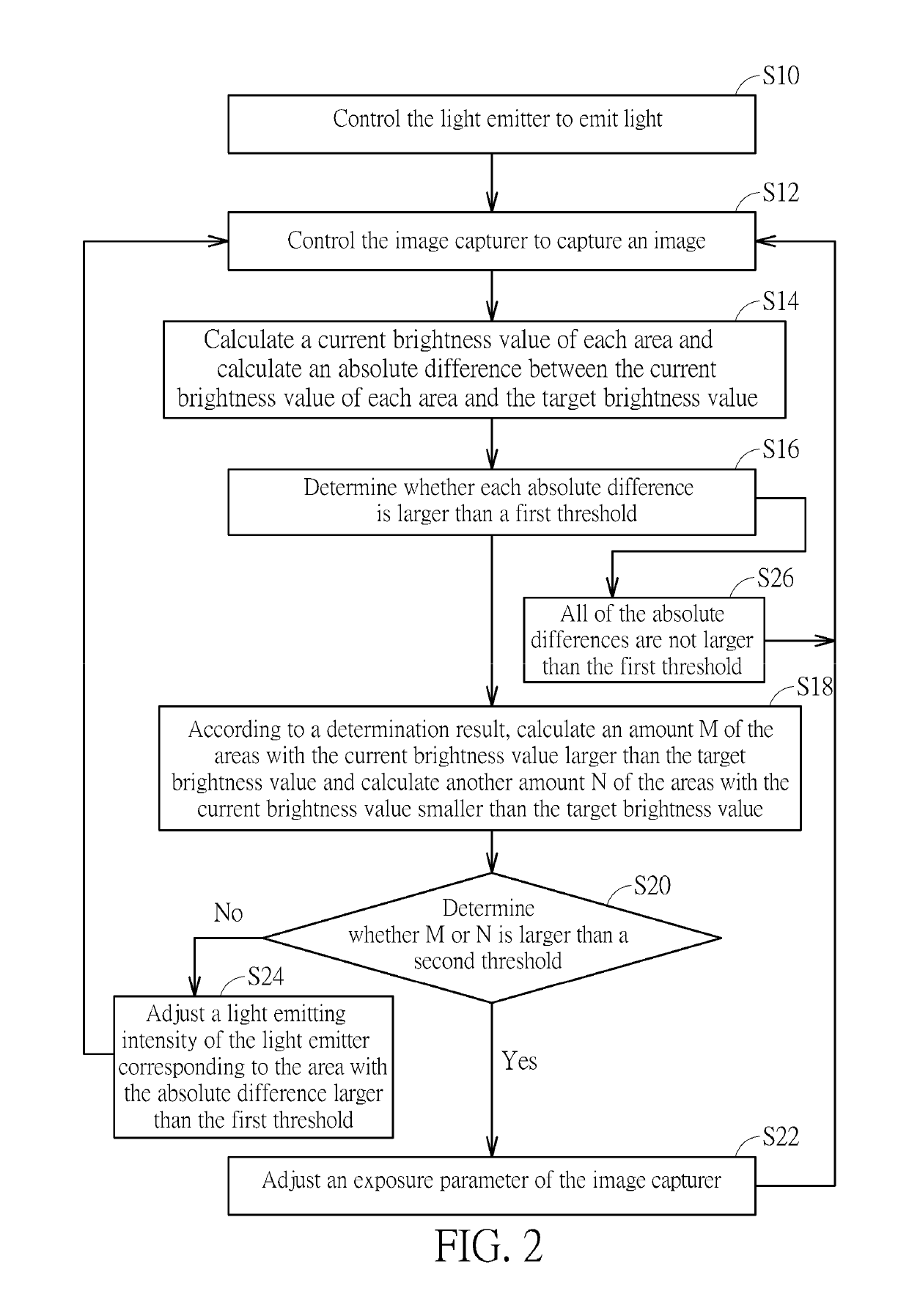
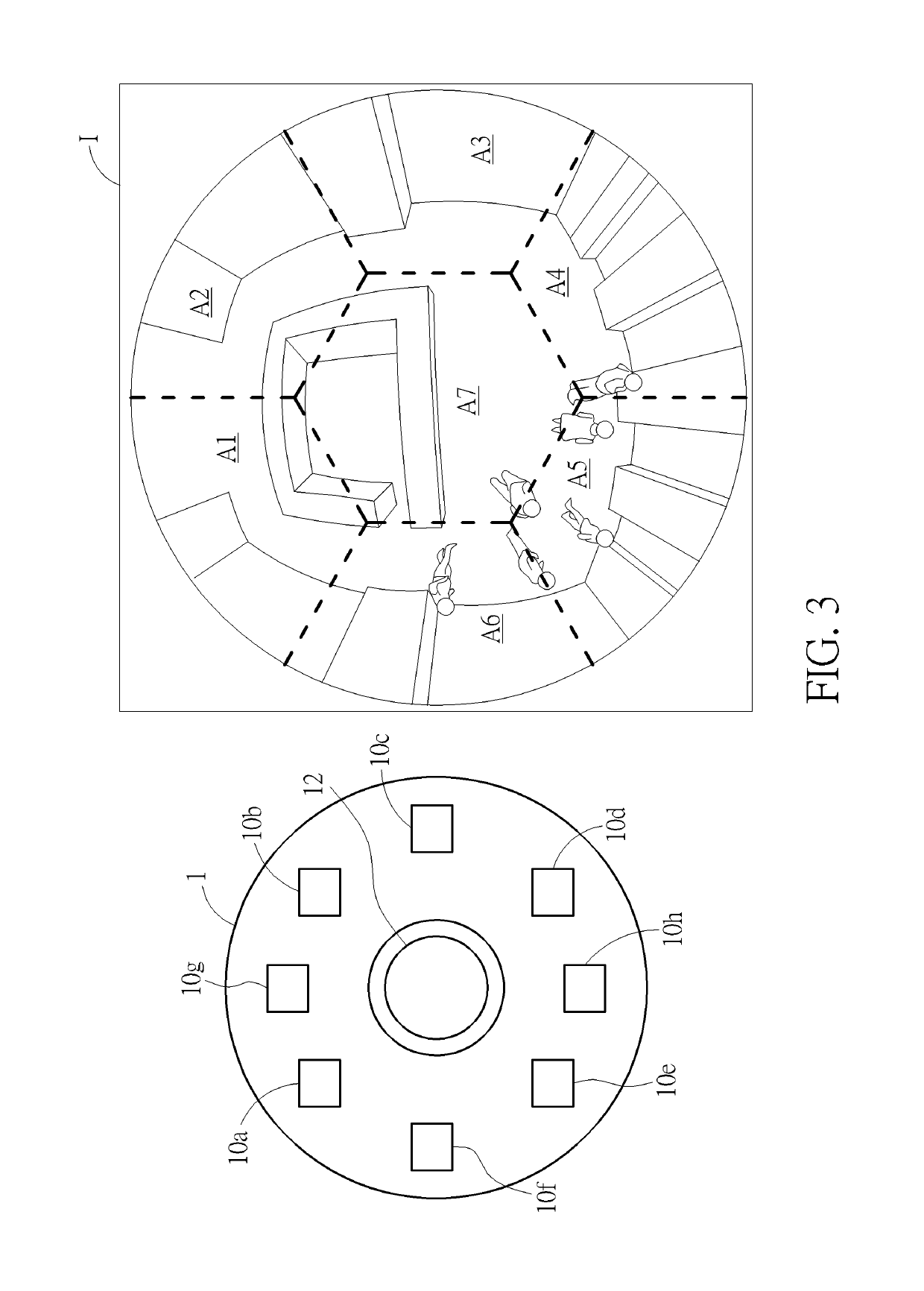
[0013]Referring to FIGS. 1 to 3, FIG. 1 is a functional block diagram illustrating an image capturing device 1 according to an embodiment of the invention, FIG. 2 is a flowchart illustrating a brightness adjusting method according to an embodiment of the invention, and FIG. 3 is a schematic diagram illustrating a relationship between the light emitters 10a-10h of the image capturing device 1 shown in FIG. 1 and the areas A1-A7 of the image I. The brightness adjusting method shown in FIG. 2 is applied to the image capturing device 1 shown in FIG. 1.

[0014]As shown in FIG. 1, the image capturing device 1 comprises a plurality of light emitters 10a-10h, an image capturer 12, a memory 14 and a processor 16, wherein the processor 16 is electrically connected to the light emitters 10a-10h, the image capturer 12 and the memory 14. In practical applications, the light emitters 10a-10h may be infrared light emitting diodes or other light sources; the image capturer 12 may be a fish-eye lens, ...


PUM


Abstract

An image capturing device includes a plurality of light emitters, an image capturer, a memory and a processor. The memory stores a target brightness value. The processor controls the light emitters to emit light and controls the image capturer to capture an image. The image is divided into a plurality of areas and the light emitted by each of the light emitters corresponds to one of the areas. The processor calculates a current brightness value of each area and calculates an absolute difference between the current brightness value of each area and the target brightness value. The processor determines whether each absolute difference is larger than a first threshold. According to a determination result, the processor adjusts an exposure parameter of the image capturer or adjusts a light emitting intensity of the light emitter corresponding to the area with the absolute difference larger than the first threshold.

Description

BACKGROUND OF THE INVENTION1. Field of the Invention[0001]The invention relates to an image capturing device and a brightness adjusting method and, more particularly, to an image capturing device and a brightness adjusting method capable of improving image visibility effectively.2. Description of the Prior Art[0002]Since safety awareness is being raised gradually, people pay much attention to safety surveillance application. So far in many public or non-public places, there are always one or more cameras installed for safety surveillance. Furthermore, some cameras are equipped with a light emitting unit (e.g. infrared light) for assisting in illuminating at night or in a dark scene, such that the camera can capture a visible image successfully. However, when an object is close to the camera, the object located in the foreground of the image may be overexposed, such that the details of the object in the image cannot be obtained. The prior art may make the object located in the foregr...

Claims


Application Information

Patent Timeline
Patent Type & Authority Patents(United States)
IPC IPC(8): H04N5/235H04N5/243H04N5/225H04N5/238H04N23/75H04N23/76
CPCH04N5/2352H04N5/2256H04N5/238H04N5/243H04N5/2353H04N5/2354H04N5/2351H04N23/56H04N23/75H04N23/76H04N23/71H04N23/73H04N23/74H04N23/72
Inventor CHEN, WEI-SHIUCHEN, SHIH-HSUAN
Owner VIVOTEK INC
Learn More