
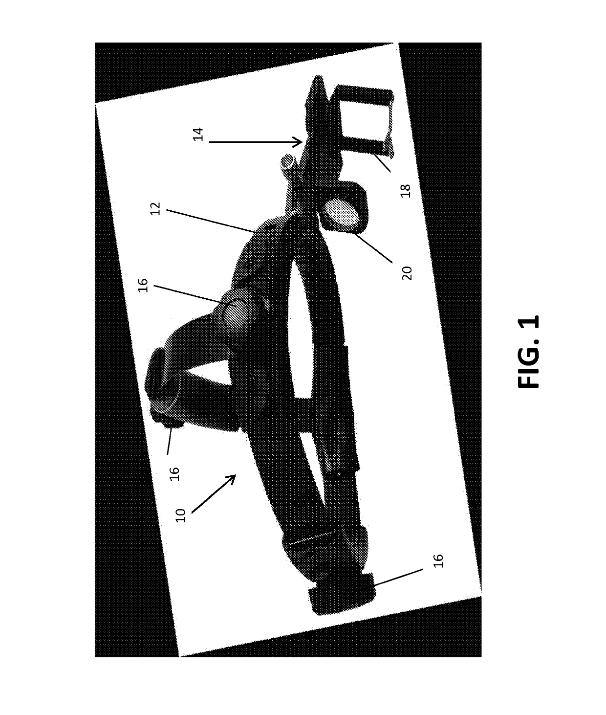
Head-mounted indirect opthalmoscope camera

a technology of indirect opthalmoscope and head-mounted camera, which is applied in the field of medical devices, can solve the problems of difficult or awkward use, high cost of portable hand-held fundus camera, and impracticality of traditional table-top fundus imaging device, and achieve the effect of reducing chromatic aberration

Active Publication Date: 2019-06-11
THE JOHN HOPKINS UNIV SCHOOL OF MEDICINE
View PDF8 Cites 0 Cited by
  • Summary
  • Abstract
  • Description
  • Claims
  • Application Information

AI Technical Summary

Benefits of technology

This patent describes a system for taking stereoscopic images of the retina. It uses a light source and a digital imaging device with a special lens to capture the images. A optical means is used to create virtual images that are then combined to create a 3D view of the retina. The system is designed to position the light source, imaging device, and optical means in a way that allows the virtual images to be separated and captured within the pupil of the eye. This creates a more realistic and accurate representation of the retina.

Problems solved by technology

Conventional table-top fundus imaging devices are impractical for some patients, such as infants, young children, and bedridden patients who cannot hold still or maneuver into the necessary position for proper eye alignment with the camera.
Many portable hand-held fundus cameras are very expensive and are difficult or awkward to use.
This occupies both hands of the examiner, with manipulation of the lids or scleral depression by the second hand no longer being possible.
In addition, most ophthalmologists are not accustomed to such a bi-manual camera aiming technique.
A head-mounted indirect ophthalmoscope with an integrated camera is ideal, but existing such devices have flaws that affect image quality.
Consequently, this indirect ophthalmoscope with an integrated camera can allow the examiner to obtain a good monocular view, but the instrument can be easily misaligned for the camera, causing vignetting and poor quality images.
Also, stereoscopic imaging of the ocular fundus is not possible with existing head-mounted indirect ophthalmoscopes.

Method used


Image

  • Head-mounted indirect opthalmoscope camera
  • Head-mounted indirect opthalmoscope camera
  • Head-mounted indirect opthalmoscope camera

Examples


Embodiment Construction

[0025]The presently disclosed subject matter now will be described more fully hereinafter with reference to the accompanying Drawings, in which some, but not all embodiments of the inventions are shown. Like numbers refer to like elements throughout. The presently disclosed subject matter may be embodied in many different forms and should not be construed as limited to the embodiments set forth herein; rather, these embodiments are provided so that this disclosure will satisfy applicable legal requirements. Indeed, many modifications and other embodiments of the presently disclosed subject matter set forth herein will come to mind to one skilled in the art to which the presently disclosed subject matter pertains, having the benefit of the teachings presented in the foregoing descriptions and the associated Drawings. Therefore, it is to be understood that the presently disclosed subject matter is not to be limited to the specific embodiments disclosed and that modifications and other...


PUM


Abstract

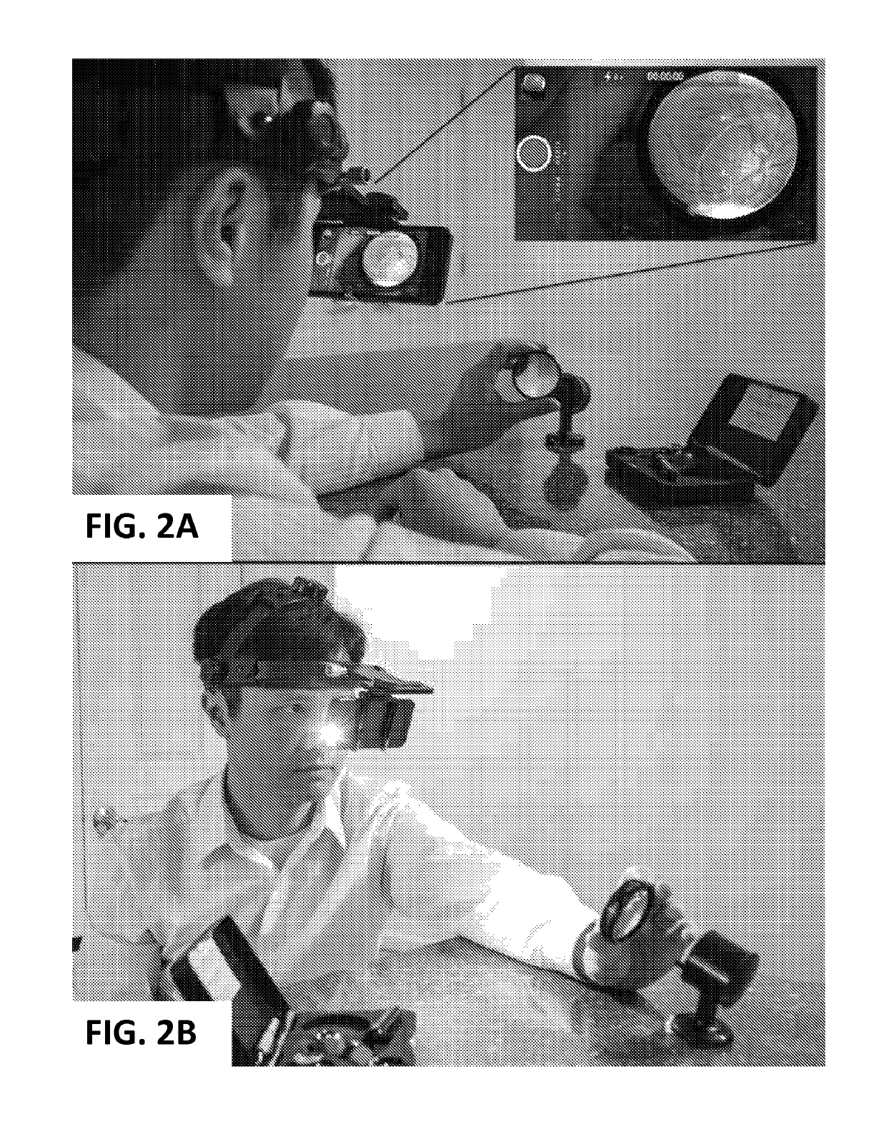
The present invention is directed to an indirect ophthalmoscopic system for imaging of the ocular fundus including a headband configured to hold a digital imaging device and a plus eyepiece lens in front of an eye of the examiner, with the plus eyepiece lens positioned in between the digital imaging device and the examiner's eye, such that the examiner is focused upon the display of the digital imaging device. The aperture of the digital imaging device receives light reflected from the ocular fundus of the patient's eye, emanating from the patient's pupil. The examiner examines the patient and composes the image of the ocular fundus directly in the display screen. In this way, what the examiner sees is captured by the digital imaging device. Stereoscopic imagery is obtained by optical means that create side-by-side virtual images of the aperture of the digital imaging device within the pupil of the eye.

Description

CROSS-REFERENCE TO RELATED APPLICATIONS[0001]This application is a 35 U.S.C. § 371 U.S. national entry of International Application PCT / US2015 / 036394, having an international filing date of Jun. 18, 2015, which claims the benefit of U.S. Provisional Application No. 62 / 034,828, filed Aug. 8, 2014, the content of each of the aforementioned applications is herein incorporated by reference in their entirety.FIELD OF THE INVENTION[0002]The present invention relates generally to medical devices. More particularly, the present invention relates to a system and method for imaging the ocular fundus and screening for eye diseases.BACKGROUND OF THE INVENTION[0003]Ocular fundus imaging is used to examine and record images of internal structures in the back the eye (the ocular fundus), including structures such as the retina, optic disc, macula, and posterior pole. Fundus imaging can be used to detect and monitor diseases that affect the eye. Conventional table-top fundus imaging devices are imp...

Claims


Application Information

Patent Timeline
Patent Type & Authority Patents(United States)
IPC IPC(8): A61B3/10A61B3/12A61B3/00H04N13/207A61B3/14H04N13/339A61B90/50
CPCA61B3/12A61B3/0008A61B3/0033A61B3/14H04N13/207H04N13/339A61B3/0083A61B2090/502
Inventor WANG, AARONAVALLONE, JOHNGUYTON, DAVID
Owner THE JOHN HOPKINS UNIV SCHOOL OF MEDICINE
Learn More