
Connecting element with profile rails

a technology of connecting elements and profile rails, applied in the direction of rod connections, fastening means, building components, etc., can solve the problems of requiring a large amount of force, the connecting element cannot be slid far enough into the profile rail, and the connecting element cannot be accessed. , to achieve the effect of increasing the height of the step, reducing the risk of displacement, and simplifying the addition of crimping

Inactive Publication Date: 2019-06-11
KNAUF GIPS KG
View PDF22 Cites 3 Cited by
  • Summary
  • Abstract
  • Description
  • Claims
  • Application Information

AI Technical Summary

Benefits of technology

This patent describes a connector that can be easily assembled and used to connect profile rails. The connector has tabs that can be positioned and slid into the profile rail, even when the position of the connecting element is concealed. The tabs provide feedback on the position and how far the connecting element is slid into the profile rail. The connector is designed with resilient legs that can adjust to dimensional deviations and can be easily attached to the profile rail using a crimping tool. A detent lug is also provided to secure the connector in place and provide visual feedback on the endpoint of the assembly. Overall, this connector makes it easy to assemble and use profile rails.

Problems solved by technology

The problem with the assembly consists in the fact that the connecting element can only be accessed with difficulty during the assembly of the last profile rail.
Since he is not able to visually check the position of the connecting element, there is also the risk of the connecting element not being slid far enough into the profile rail positioned last.
The problem is made worse by the fact that the profile rails are produced in a relatively imprecise manner, so that occasionally the displacement requires a great deal of force.

Method used


Image

  • Connecting element with profile rails
  • Connecting element with profile rails
  • Connecting element with profile rails

Examples


Embodiment Construction

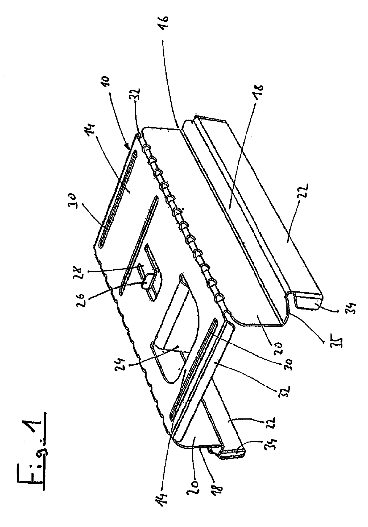
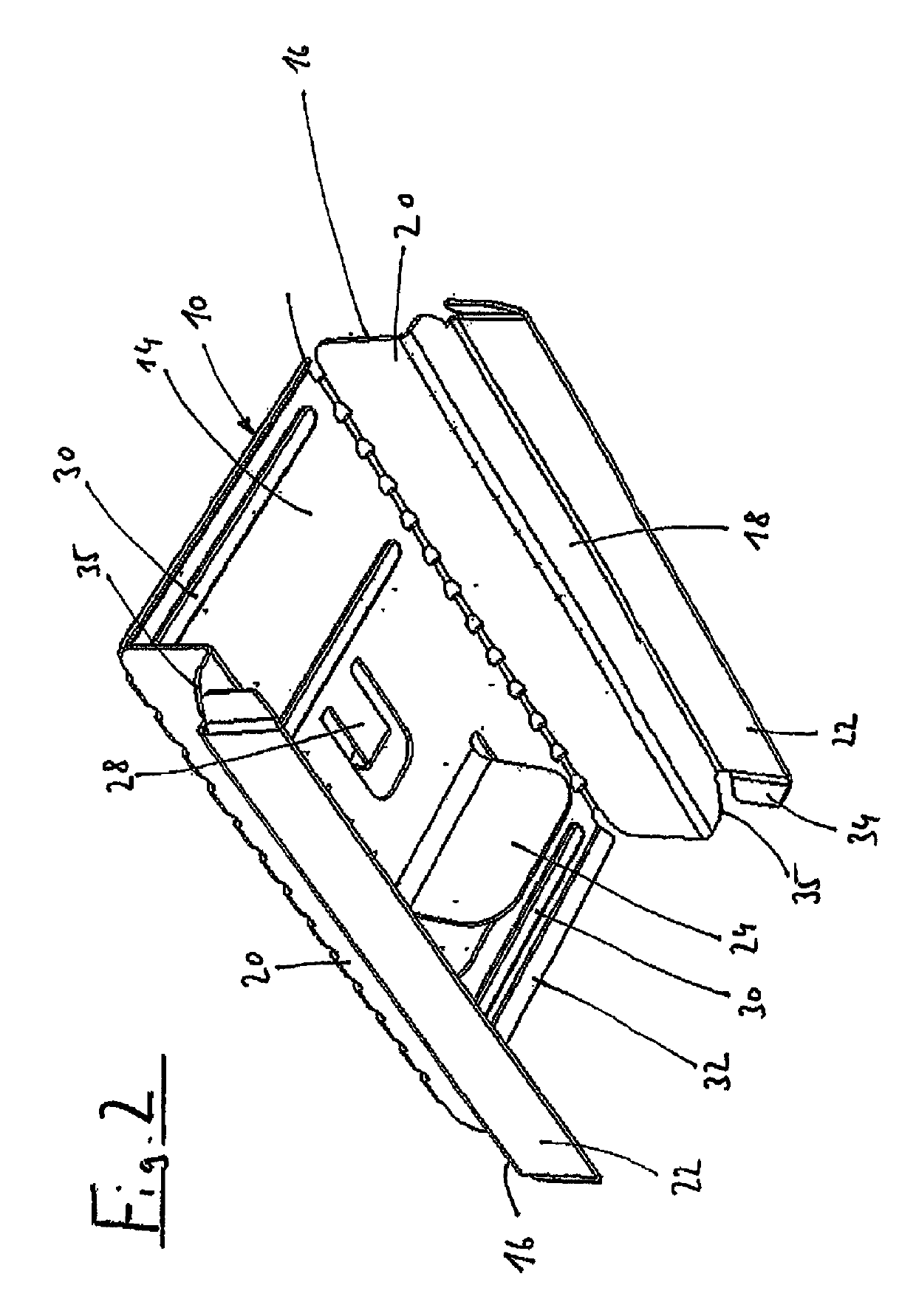
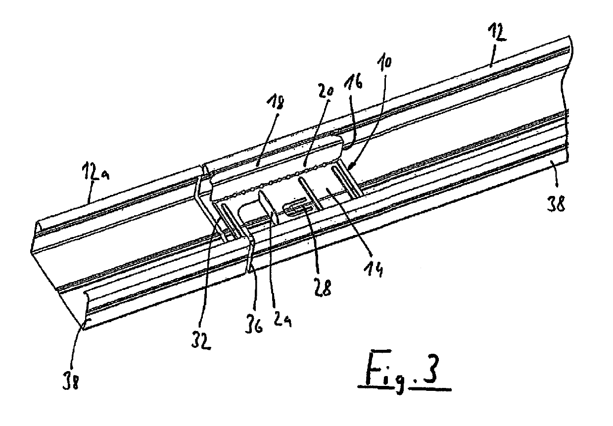
[0018]FIG. 1 shows a connecting element 10, which is intended for connecting C-shaped profile rails 12 (see FIGS. 3 and 4), when the latter lie aligned with one another. The connecting element comprises a holding plate 14 with lateral legs 16 and is formed in one piece completely from sheet metal. The lateral legs are divided by shoulders 18 into connecting regions with a smaller distance from one another and edge regions 22, wherein the spacing of edge regions 22 is adapted to the width of the profile rails to be connected, so that the outer surfaces of these regions 22 can lie with a contact area against the inner sides of the profile rails. The stepped structure of the legs enables elastic yielding of edge regions 22 inwards, so that in the initial state the spacing of the outer surfaces of these regions can be slightly greater than the inner width of the profile rails. Especially with regard to measurement tolerances in the commercially available C-shaped profile rails, this can...


PUM


Abstract

The invention relates to a connecting element for connecting two aligned C-shaped profile rails (12). The connecting in element (10) is in the form of a sheet metal profile the cross-section of which, adapted to the profile rails (12) to be connected, is such that said sheet-metal profile can be slid into said profile rails (12) from the fronts thereof in a captive manner. A handling tab (14) that is accessible after the connecting element has been slid into a profile rail (12) is moulded onto or mounted on said connecting element.

Description

CROSS-REFERENCE TO RELATED APPLICATIONS[0001]This application is the United States national phase of International Application No. PCT / EP2014 / 002304 filed Aug. 22, 2014, and claims priority to German Patent Application No. 20 2013 007 676.3 filed Aug. 28, 2013, the disclosures of which are hereby incorporated in their entirety by reference.BACKGROUND OF THE INVENTION[0002]Field of the Invention[0003]The present invention relates to a connecting element for connecting two aligned C-shaped profile rails, wherein the connecting element is constituted as a sheet metal profile, the cross-section whereof, adapted to the profile rails to be connected, is constituted in such a way that said sheet metal profile can be slid from the front sides thereof into the profile rails in a captive manner.[0004]Description of Related Art[0005]Such connecting elements are widely known. They usually sit with very little play in the profile rails, in order to be able to duly connect the latter as far as po...

Claims


Application Information

Patent Timeline
Patent Type & Authority Patents(United States)
IPC IPC(8): F16B7/04E04B9/10E04B9/24
CPCF16B7/0413E04B9/247E04B9/10Y10T403/55
Inventor HUWER, THOMAS
Owner KNAUF GIPS KG
Learn More