
Multi-configurable corneal surface marker

a corneal surface marker and multi-configurable technology, applied in the field of multi-configurable corneal surface markers, can solve the problems of poor surgical outcomes and failure of most marking components in the prior art, and achieve the effect of reducing the potential of patient flinching or moving, and being convenient to us

Inactive Publication Date: 2013-03-07
SUNALP MURAD A
View PDF4 Cites 0 Cited by
  • Summary
  • Abstract
  • Description
  • Claims
  • Application Information

AI Technical Summary

Benefits of technology

The patent describes a corneal marking device that uses light to help with procedures that involve the eye. The device is designed to be easily adjusted for different procedures and is designed to make the patient's view of the approaching marker invisible to reduce flinching or eye movement. The technical effects of this device include improved accuracy and safety during corneal marking procedures and reduced patient discomfort.

Problems solved by technology

However, most marking components in the prior art fail to take into consideration, the angst of the patient from the marking device approaching their eyeball and the need to consistently align the axis of the radial marking device, with the center axis of the eye running through the center of the pupil.
Small inaccuracies in planning can, and usually do lead to poor surgical outcomes.

Method used


Image

  • Multi-configurable corneal surface marker
  • Multi-configurable corneal surface marker
  • Multi-configurable corneal surface marker

Examples


Embodiment Construction

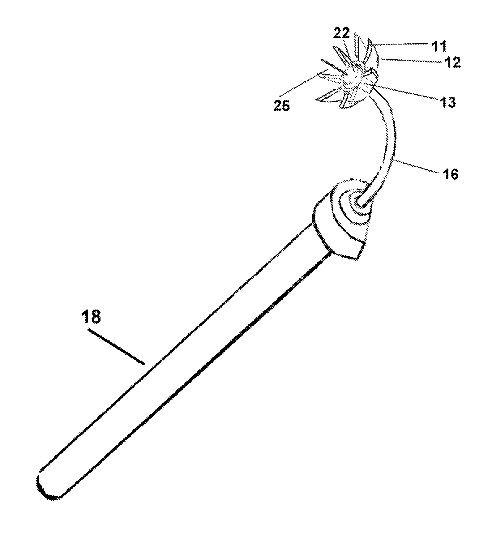
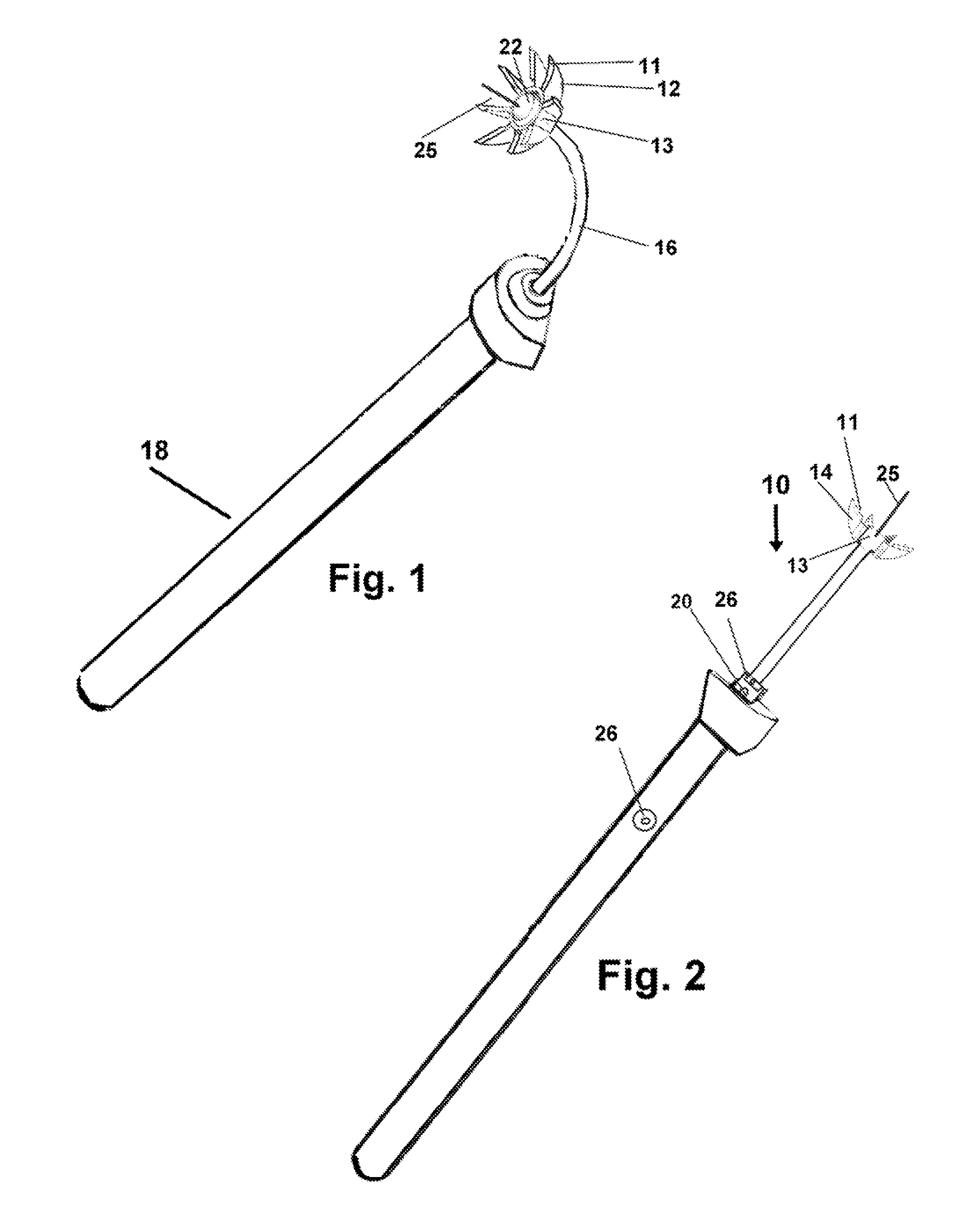
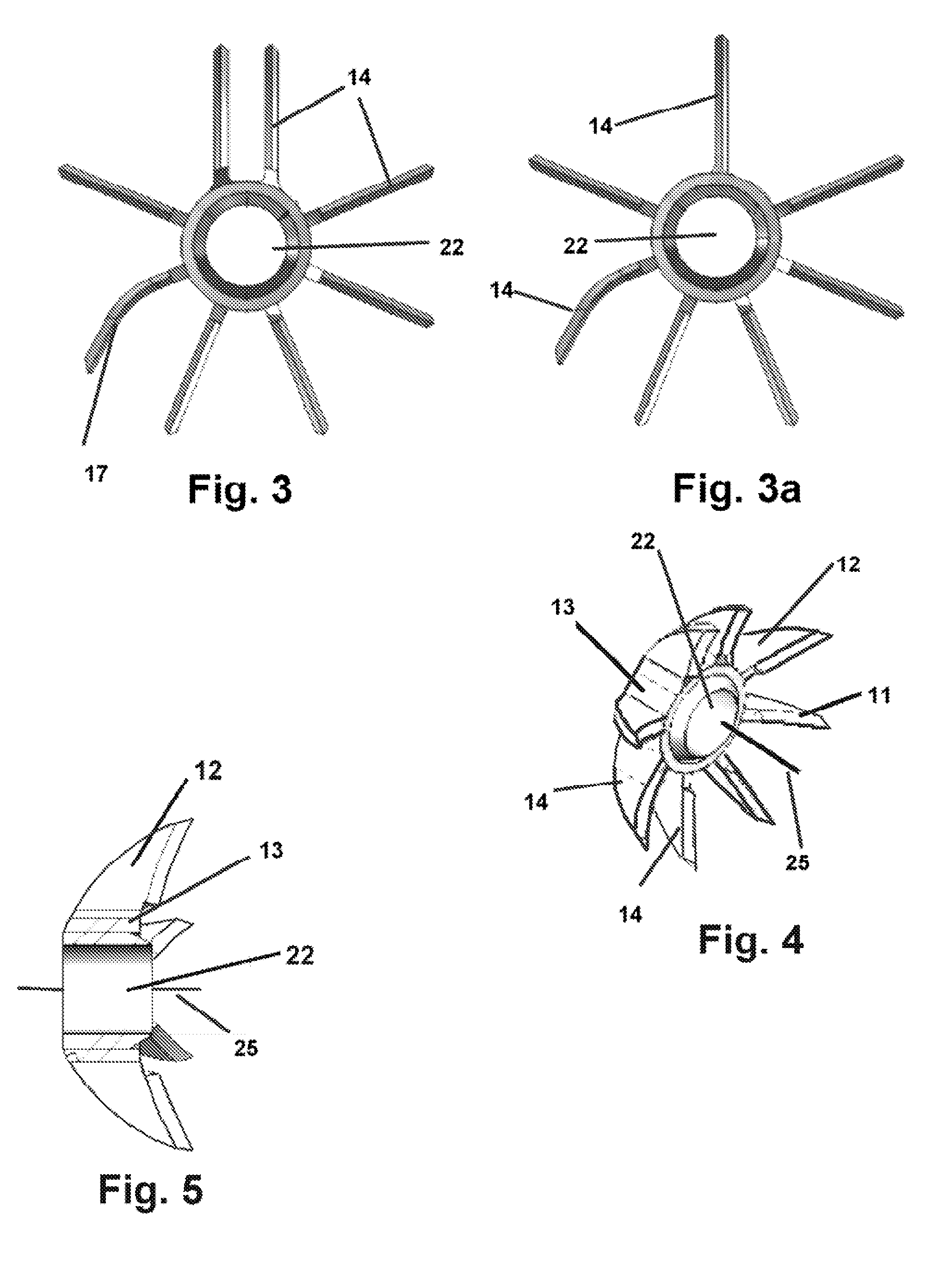
[0039]Referring now to the FIGS. 1-15, the radial eye marker device 10 which may be employed for corneal marking using ink or marking liquid placed on the curved frontal surfaces 11 of the curved mounting members 12 forming the radially deployed curved marking fins 14 or by making indents in the cornea therewith or both.

[0040]The device 10 may employ one or may have a kit featuring a plurality of marking components 13 having marking fins 14 formed by curved mounting members 12 radially deployed around a central hub 22 and having a curve to the frontal surfaces mirroring the curve of the corneal surface of an eyeball and in a manner adapted to the purpose intended. All the marking fins 14 are radially extending from the hub 22 which is engaged to the distal end of the curved or a flexible mounting member 16. The mounting member 16 may be fixed in a curve or may be flexible to a curve.

[0041]The mounting member 16 is engaged at a proximal end to a handle 18 with a communicating light s...


PUM


Abstract

A corneal marking device for placing markings on the cornea of a patient. The device features a mounting member which is adapted for a hand gripping on one end and has a corneal marking component at the other. The marking component has a centrally located hub having an axial passage and has a plurality of marking fins radially extending from said hub. The leading edge of the fins of said marking component are adapted for placement of ink thereon which is communicated to the eye on contact. A light source communicating from the hub masks the approach of the device to the patient's eye diminishing patient flinching and eye movement. A two colored communication of the light source to the eye provides the user a visual reference to maintain the device in alignment with the patient's eye until contact.

Description

[0001]This application claims priority to U.S. Provisional Application Serial Number 61 / 37996 filed on September 2, 2010 and is included herein in its entirety by reference. The invention herein disclosed relates generally to medical devices and tools adapted for employment with eye surgery and treatment. More particularly it relates to an instrument for medical professionals to employ for placing radial, horizontal, and vertical reference meridians upon the corneal surface to mark and to evaluate corneal topography.BACKGROUND OF THE INVENTION[0002]1. Field of the Invention[0003]2. Prior Art[0004]Surgical treatment for many eye diseases and imperfections has evolved modernly into many different types of procedures. In carrying out a majority of such procedures it is extremely important that the surgeon be able to evaluate the corneal topography. Further, it is equally important that the eye of the patent be marked accurately to insure the most favorable outcome.[0005]However, most m...

Claims


Application Information

Patent Timeline
Patent Type & Authority Applications(United States)
IPC IPC(8): A61F9/007
CPCA61F9/0136
Inventor SUNALP, MURAD A.
Owner SUNALP MURAD A
Learn More