
Door handle assembly for a vehicle

a technology for a door handle and a vehicle, which is applied in the field of door handle arrangement for a motor vehicle, can solve the problems of user's hand holding, requiring a great deal of effort, and the emergency action of opening the vehicle door is not very user-friendly, so as to reduce production costs and installation time

Active Publication Date: 2017-06-08
HUF HULSBECK & FURST GMBH & CO KG
View PDF1 Cites 0 Cited by
  • Summary
  • Abstract
  • Description
  • Claims
  • Application Information

AI Technical Summary

Benefits of technology

This invention is a door handle arrangement that has a cover for the locking cylinder when in its rest position. The handle can be pivoted into a release position to activate the locking cylinder. The handle is held in the release position after it reaches the end of its movement path by the locking means, which ensures that the handle is retained in the release position. This makes it easier for the user to insert a key into the locking cylinder. The handle has a cavity that receives the locking cylinder and is protected from impact and environmental influences. The locking means also acts as the reset means, which simplifies the structure and reduces production and installation time. The flexible spring element acts as the locking means and can be mounted either on the support or on the handle. This simplifies the assembly compared to attaching the locking means at a movable component. Overall, this invention provides a more convenient and easy-to-use door handle arrangement.

Problems solved by technology

However, because of temporary or permanent interruptions or, for example, an empty battery of equipment required for the electronic access function, a mechanical emergency or auxiliary locking device is formed on at least one door handle arrangement of the vehicle.
However, this well-known door handle arrangement has the disadvantage that the user has to hold the handle with one hand in the release position, while using the other hand to insert the key into the locking cylinder in order to perform the locking function.
At the same time, the user has to hold the handle in the release position against a reset force, which can require a great deal of effort.
Consequently, in the well-known door handle arrangement, the emergency action of opening the vehicle door is not very user-friendly.

Method used


Image

  • Door handle assembly for a vehicle
  • Door handle assembly for a vehicle
  • Door handle assembly for a vehicle

Examples


first embodiment

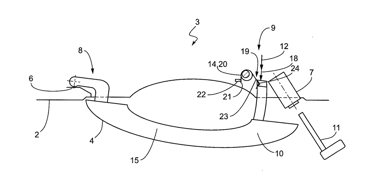
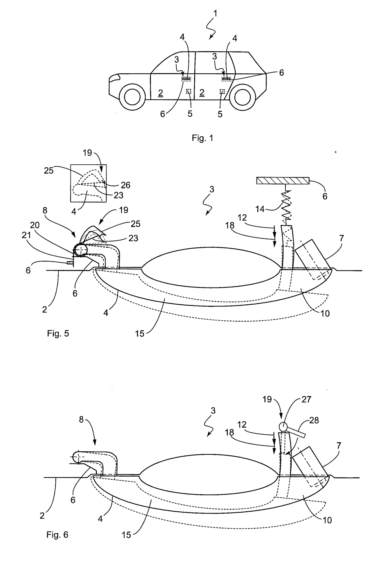
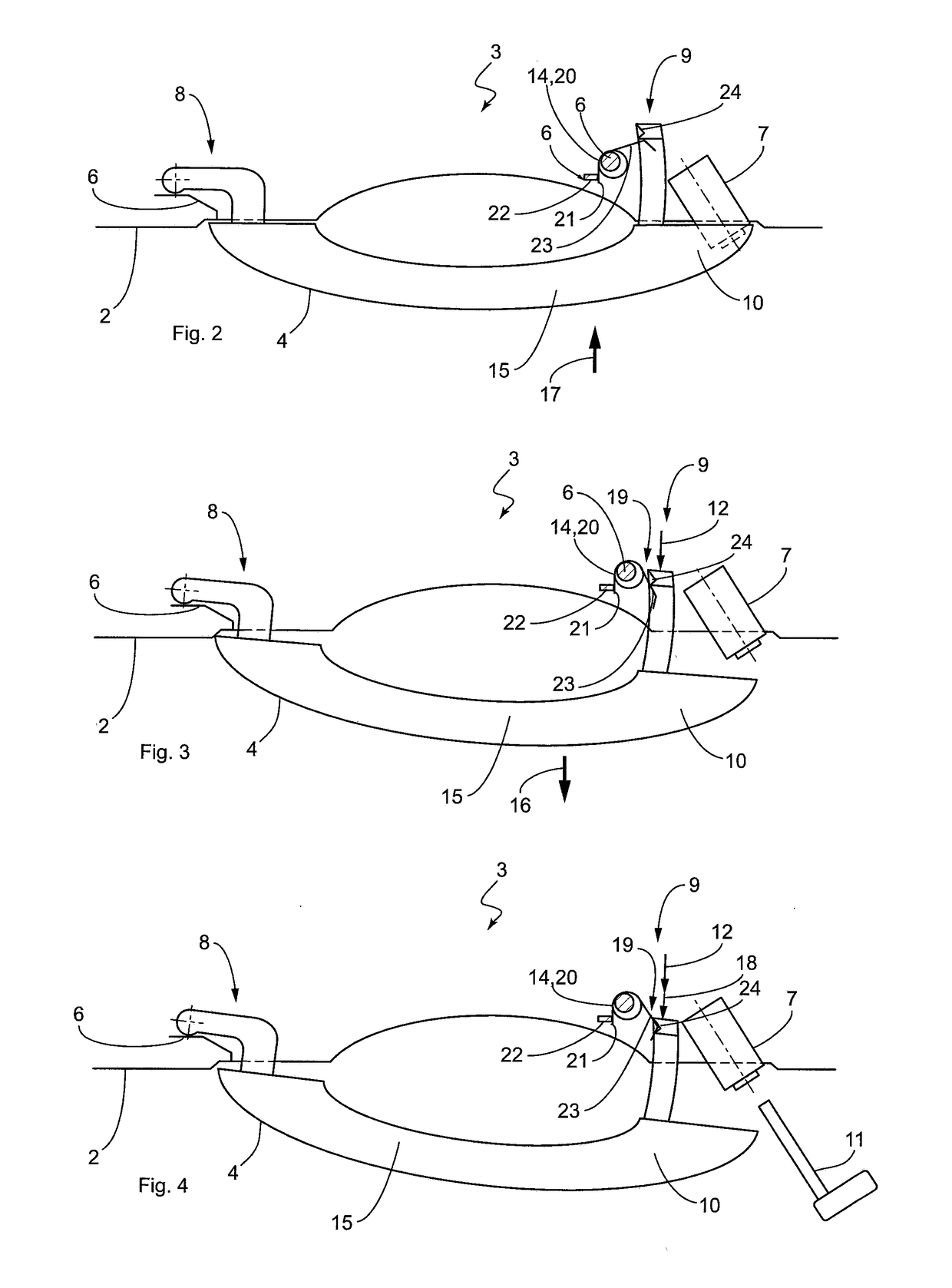
[0024]FIGS. 2 to 4 show the invention-based door handle arrangement 3, which comprises a handle 4, the support, which is indicated only schematically, as well as a locking cylinder 7. The locking cylinder 7 is also fixed at the support and is covered by the handle 4 in its rest position, as shown in FIG. 2. An overview of FIGS. 2 to 4 shows that a first longitudinal end 8 of the handle 4 is mounted on the support 6 in such a way that it can be swiveled over a bearing section. A second longitudinal end 9 of the handle 4 is coupled at the support in such a way that it can be moved away from the door 4. In the present example, the handle 4 is shown to be hollow. However, it can contain any electronic communication devices or other mechanical components and elements. Since they are not relevant for the present invention, they are not shown.

[0025]In the longitudinal extension at the second longitudinal end 9 of the handle 4, there is a cavity or receiving space which partially receives t...

second embodiment

[0031]FIG. 5 shows the invention. The door handle arrangement 3 shown there comprises the handle 4, the locking cylinder 7 and the support 6, which is indicated only schematically. The handle 4 is pushed by the resetting device 14 into its rest position, wherein the resetting device 14 is designed in the form of a spring, which in the embodiment shown is fixed with one end at the support 6, while the other end is attached at the grip hook of the handle 4. FIG. 5 shows the rest position of the handle 4 by means of a continuous line and the release position by means of a dotted line. For reasons of clarity, the actuated position, which occurs between the rest position and the release position, is not shown.

[0032]Consequently, an actuation of the handle 4 takes place against the spring force of the resetting device 14, wherein it is obvious that a deflection of the handle 4 beyond the first movement path 12 requires a greater force than for a normal actuation of the handle 4. In a case...

third embodiment

[0033]FIG. 6 shows the present invention, wherein the structure of the door handle arrangement 3, as well as its function, is mostly identical with the other two embodiments, so that it is not necessary to provide another detailed description. Subsequently, we will address merely the differences to the other two embodiments. The door handle arrangement 3 again comprises the handle 4, the locking cylinder 7, the support 6 on which the handle 4 is mounted in the way described above and to which the locking cylinder is attached, a resetting device (not shown in FIG. 6) which pushes the handle 4 into its rest position, and the locking means 19. The locking means 19 is arranged at the second longitudinal end 9 of the handle 4 and mounted to the support 6 or a different fixed part of the door 4 (in relation to the swivel-mounted handle 4). The locking means 19 can be rotated about a rotational axis 27, wherein a spring preload ensures that the locking means 19 is rotated in clockwise dire...


PUM


Abstract

A door handle arrangement for a motor vehicle, includes a support, a handle that is swivel-mounted on the support to be moved between a rest position and an actuated position along a first movement path, a locking cylinder and a resetting device. The handle can be pivoted with respect to the locking cylinder into a release position in such a way that it can be lifted off the locking cylinder and the locking cylinder is released for inserting a key. The handle is designed in such a way that it can be pivoted from the actuated position along a second movement path, which is adjacent to the first movement path, into the release position, wherein in the release position of the handle, the handle is retained in its release position by a locking element.

Description

BACKGROUND[0001]The invention relates to a door handle arrangement for a motor vehicle, which has a support that can be mounted on the inside of a door of the motor vehicle, a handle that can be arranged on the outside of the vehicle door and that is swivel-mounted on the support to be moved between a rest position and an actuated position along a first movement path and to be grasped by a user, a locking cylinder and a cover for the locking cylinder and a resetting device that pushes the handle with a reset force into rest position, wherein the handle is designed in such a way that it forms in rest position the cover for the locking cylinder, wherein a first longitudinal end of the handle is swivel-mounted on the support and a second longitudinal end of the handle is coupled with the support and can be moved away from the support, wherein the handle can be pivoted with respect to the locking cylinder into a release position in such a way that it can be lifted off the locking cylind...

Claims


Application Information

Patent Timeline
Patent Type & Authority Applications(United States)
IPC IPC(8): E05B81/90E05B85/16E05B85/06
CPCE05B81/90E05B85/16E05B85/06E05B15/0053E05B81/78E05B79/10E05B79/06E05B79/20
Inventor BECK, ANDREAS
Owner HUF HULSBECK & FURST GMBH & CO KG
Learn More