Toner collection container and image forming device including the same

a technology of image forming device and toner collection container, which is applied in the direction of optics, electrographic process apparatus, instruments, etc., can solve the problems of damage to the boundary with other parts, dented or cracked, and direct impact damage to the outer surface of the container, so as to prevent damage by impact, prevent airflow inside the image forming device, and keep a sufficient amount of waste toner

Active Publication Date: 2019-06-11
KONICA MINOLTA INC
View PDF8 Cites 0 Cited by
  • Summary
  • Abstract
  • Description
  • Claims
  • Application Information

AI Technical Summary

Benefits of technology

[0011]An object of the present invention is to solve the above-described problems, and particularly to provide a toner collection container that: prevents damage by impact in a fall and deformation caused by the weight of the waste toner regardless of strength and rigidity of a material; and does not hinder an airflow inside an image forming device even while keeping a sufficiently large storable amount of waste toner.

Problems solved by technology

In a case where a user mistakenly slips a container out of the hand and drops the same on a floor at the time of replacement, an outer surface of the container subjected to direct impact of the floor is likely to be damaged, for example, dented or cracked.
Furthermore, at the moment of collision with the floor, pressure (powder pressure) of stored waste toner rapidly is concentrated on a part of an inner face of the container close to the floor, and therefore, a boundary with other parts is likely to be damaged, for example, flawed.
The reason is that rigidity of a typical material thereof is low.
In a case where the container is excessively deformed, a full-state detection error by the toner sensor of the image forming device may exceed an allowable range.
However, in this case, treatment after being discarded becomes difficult, and moreover, a low manufacturing cost can be hardly kept.
In recent years, it is further difficult to prevent a toner collection container from hindering an airflow inside an image forming device while keeping a sufficiently large storable amount of waste toner.

Method used


Image

  • Toner collection container and image forming device including the same
  • Toner collection container and image forming device including the same
  • Toner collection container and image forming device including the same

Examples


embodiment

Advantages of Embodiment

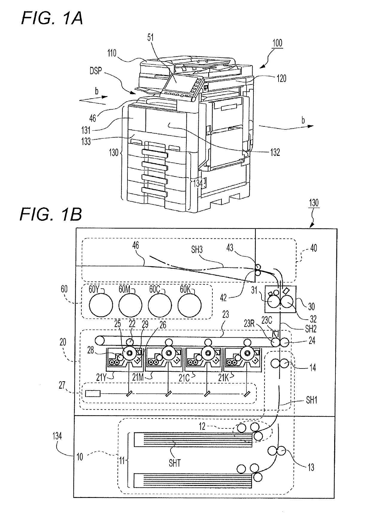
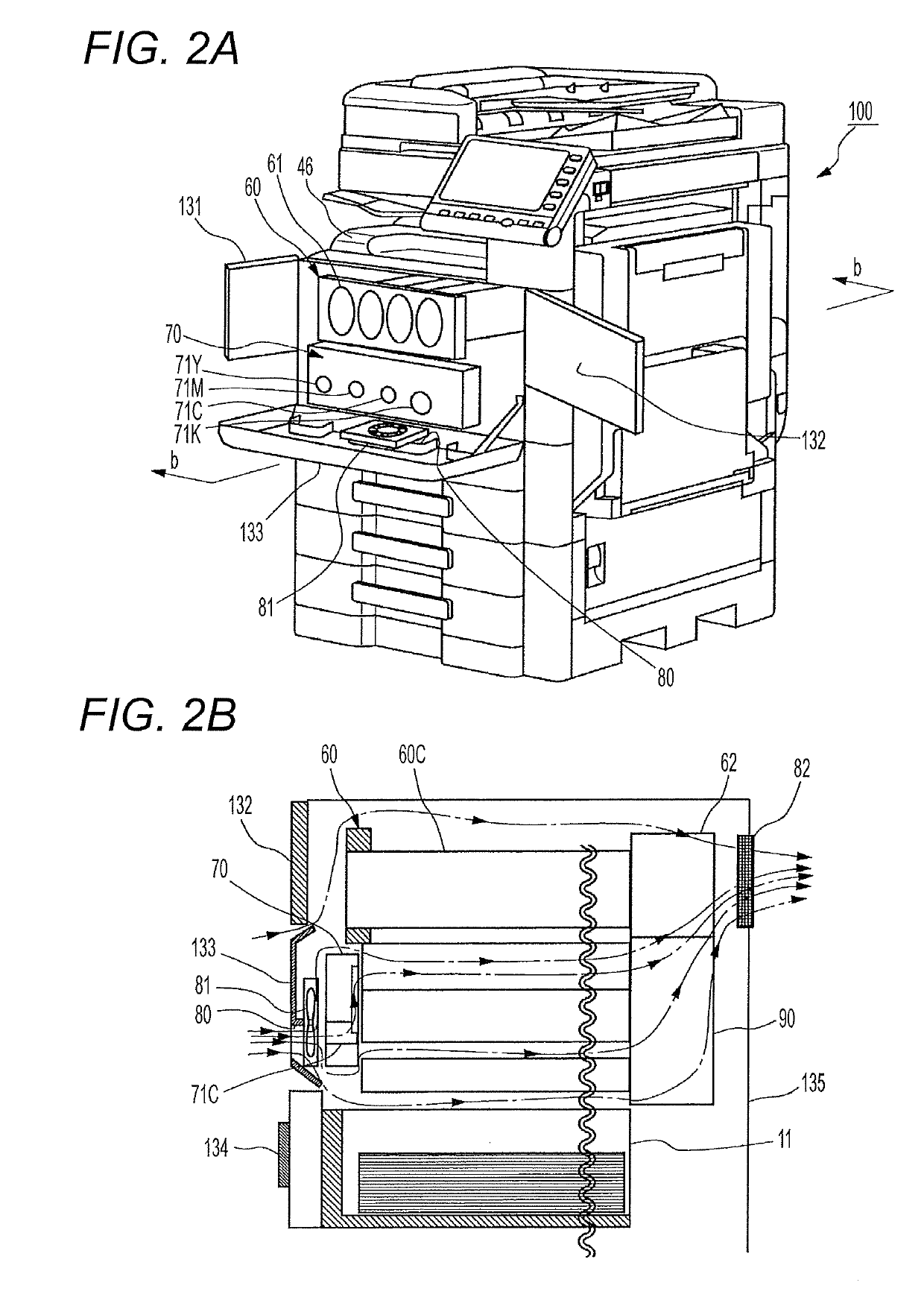
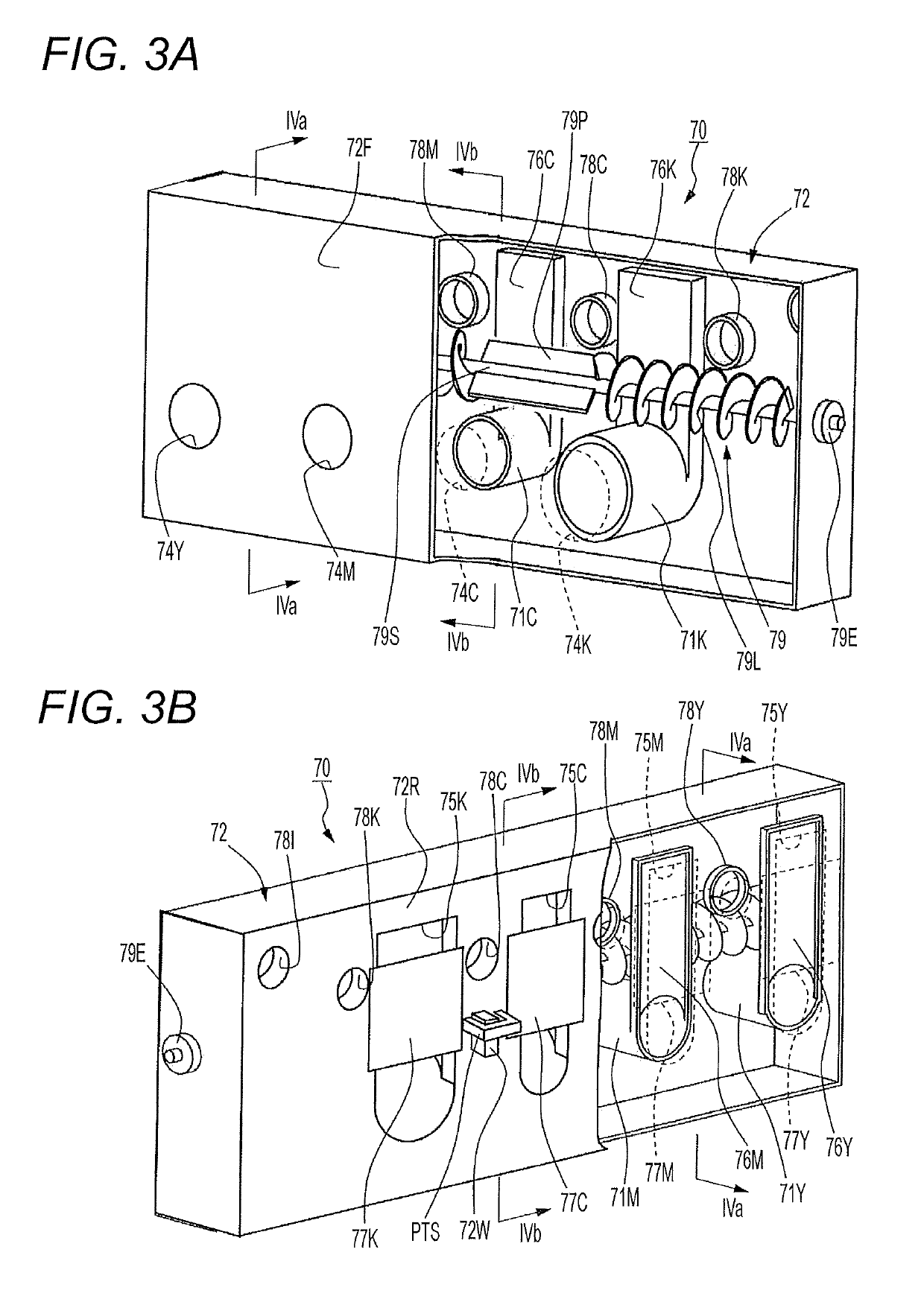
[0075]As described above, the toner collection container 70 according to the embodiment of the present invention has the housing 72 incorporated between the air inlet port 80 and the image former 20 of the printer 130. The four ducts 71Y to 71K penetrate the storing region STR inside the housing 72 from the front wall 72F to the rear wall 72R of the housing 72, and guide the external air flowing from the air inlet port 80 to the side where the image former 20 is positioned. Since the ducts 71Y to 71K function as the “beams” in the structure of the housing 72, the housing 72 has high strength and rigidity regardless of strength and rigidity of a material thereof. Thus, the toner collection container 70 prevents damage by impact in a fall and deformation caused by the weight of the waste toner regardless of the strength and rigidity of the material, and does not hinder an airflow inside the printer 130 even while keeping a sufficiently large storable amount of ...

modified examples

[0076](A) The image forming device 100 illustrated in FIGS. 1A and 1B is a color print compliant MFP. The image forming device according to the embodiment of the present invention may also be a monochrome MFP dedicated to monochrome or a single function machine such as a printer, a copier, or a facsimile machine.

[0077](B) An outer shape of the housing 72 of the toner collection container 70 illustrated in FIGS. 3A, 3B, 4A, and 4B is merely an example, and may be changed in accordance with a shape of a surrounding member inside the printer 130, or may be changed for user friendliness. Similarly, a duct shape is not limited to the cylindrical shapes of the ducts 71Y to 71K in which radii are uniform in the axial direction, and may be a shape having an elliptical or polygonal cross-section. As far as a duct has a structure penetrating the storing region, strength of the storing region can be kept sufficiently high without hindering an airflow inside the printer 130 regardless of the de...


PUM


Abstract

A toner collection container detachably incorporated in an electrophotographic image forming device in order to collect toner to be discarded from an image former of the device includes: a housing including a hollow capable of storing discarded toner, and incorporated between an air inlet port and the image former in a space surrounded by a chassis of the image forming device; and at least one duct being formed of a cylindrical or tubular member that penetrates a storing region in the hollow of the housing from a side closer to the air inlet port to a side closer to the image former out of side walls of the housing, or formed of a recess included in a bottom surface of the housing and recessed toward the storing region, the duct guiding external air flowing from the air inlet port to a side where the image former is positioned.

Description

[0001]The entire disclosure of Japanese patent Application No. 2017-132619, filed on Jul. 6, 2017, is incorporated herein by reference in its entirety.BACKGROUNDTechnological Field[0002]The present invention relates to an image forming device, and particularly relates to a structure of a toner collection container.Description of the Related Art[0003]An electrophotographic image forming device such as a laser printer, a copying machine, or a multifunction peripheral (MFP) generally has a toner collection container (refer to JP 2016-138984 A, JP 2016-045353A, and JP 05-066643A). The “toner collection container” represents a container in order that an electrophotographic image forming device may store toner removed from a photoreceptor or an intermediate transfer member mainly in a cleaning step. The image forming device forms a toner image on a surface of the photoreceptor and transfers the toner image directly from the photoreceptor to a sheet via the intermediate transfer member. Ge...

Claims


Application Information

Patent Timeline
Patent Type & Authority Patents(United States)
IPC IPC(8): G03G15/08G03G21/10G03G21/20
CPCG03G21/10G03G15/0856G03G21/206G03G15/0875G03G2215/0894
Inventor SUENAGA, TAKENORIKISHI, HIDEHITO
Owner KONICA MINOLTA INC
Why Eureka
Try Eureka