
Device, method and packaging machine for processing a packaging container

a packaging container and packaging machine technology, applied in the direction of transportation and packaging, rigid containers, bundling articles, etc., can solve the problem of particularly small moving loads, and achieve the effect of simple and efficient manner

Inactive Publication Date: 2019-06-18
SYNTEGON PACKAGING SYST AG
View PDF6 Cites 0 Cited by
  • Summary
  • Abstract
  • Description
  • Claims
  • Application Information

AI Technical Summary

Benefits of technology

[0003]As a result of the development according to the invention of the device for processing at least one packaging container, a processing step can be carried out in a particularly flexible and advantageous manner. In particular, a path of active means of the pairs of pivot arms necessary for the processing step can be established in two degrees of freedom. The device can be particularly compact and can be especially suitable for retrofitting existing packaging machines. The device can also be realized as an exchangeable module. The device can simply be attachable to and removable from several packaging machines and / or can be exchanged between several packaging machines. The movement of the pairs of pivot arms in two degrees of freedom can be driven by only two drive movements and consequently only two independent drives. The device can be particularly cost-efficient. In a preferred manner, the drives can be arranged in a stationary manner on a machine base of the device. Moving loads can be particularly small. Moving energy-conducting elements, such as, in particular, current and / or pneumatic lines, can be avoided. In particular, the displacement movement and the rotational movement can be driven by the stationary drives. A moving load is able to be reduced, in particular compared to a device with rotary drives which are displaced in the displacement movements together with the pivot arms.
[0018]It is further proposed that the coupler mechanism comprises rotary coupling means which are provided for the purpose of generating the at least one first rotational movement from a relative movement of the second advance movement with reference in each case to the at least one first pivot arm rotational axes and the at least one second rotational movement from a relative movement of the second return movement with reference in each case to the at least one second pivot arm rotational axes. It can be provided in a variant that the coupler mechanism comprises rotary coupling means which are provided for the purpose of generating the at least one second rotational movement from a relative movement of the second advance movement with reference in each case to the at least one second pivot arm rotational axes and the at least one first rotational movement from a relative movement of the second return movement with reference in each case to the at least one first pivot arm rotational axes. A “relative movement” is to be understood in this context as a resultant movement difference between two movements. The rotational movement can be generated by the rotary coupling means comprising pivotally mounted means which flexibly connect the second mechanism element, in a region in which it comprises the second advance movement, to the at least one first pivot arm in a radius outside the pivot arm rotational axis of said pivot arm and by the rotary coupling means comprising further pivotally mounted means which flexibly connect the second mechanism element, in a region in which it comprises the second return movement, to the at least one second pivot arm in a radius outside the pivot arm rotational axis of said pivot arm. In a preferred manner, the first and the second pivot arms can comprise drive wheels, in particular toothed wheels, which are arranged about the first and the second pivot arm rotational axes. The coupler mechanism can comprise at least one coupling means which transmits the second advance movement to a circumference of an at least one first toothed wheel of the at least one first pivot arm, and can comprise at least one coupling means which transmits the second return movement to a circumference of an at least one second toothed wheel of the at least one second pivot arm. The coupler mechanism can comprise, in particular, toothed belts and / or toothed rods for the transmission. The at least one first pivot arm and the at least one second pivot arm can be driven in a particularly simple manner in the synchronous first and second advance and return movements which are in opposite directions to one another and in the synchronous first and second rotational movements which are in opposite directions to one another. The control unit of the drive units can control the first and second drive movements such that the first and second pivot arms carry out the desired first and second displacement movements and the desired first and second pivoting movements.

Problems solved by technology

Moving loads can be particularly small.

Method used


Image

  • Device, method and packaging machine for processing a packaging container
  • Device, method and packaging machine for processing a packaging container
  • Device, method and packaging machine for processing a packaging container

Examples


Embodiment Construction

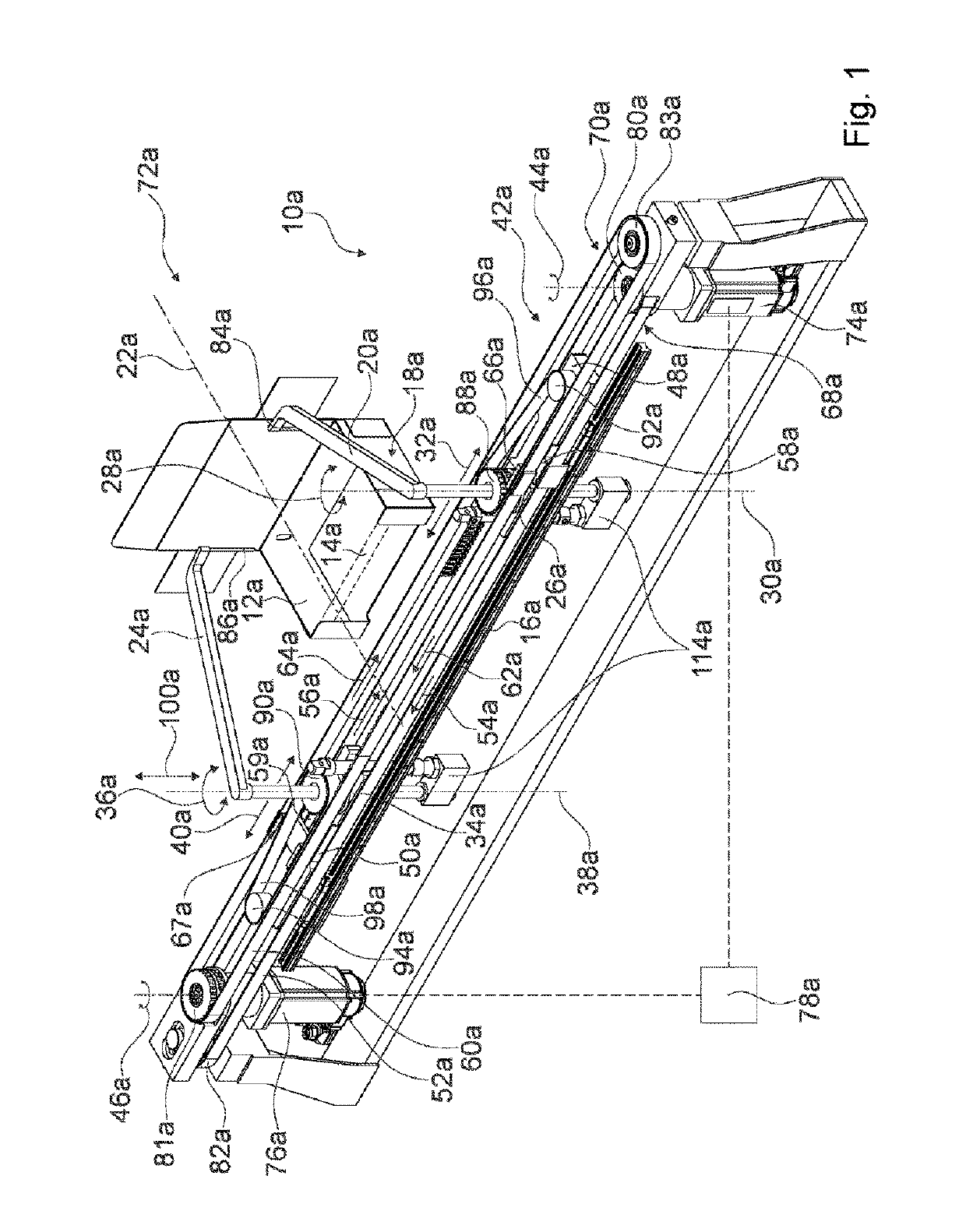
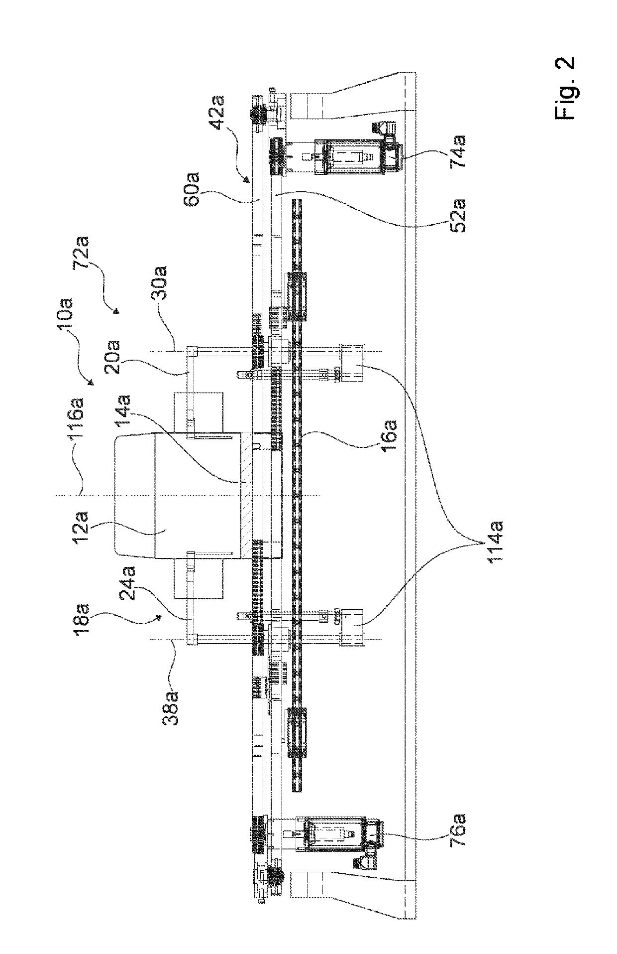
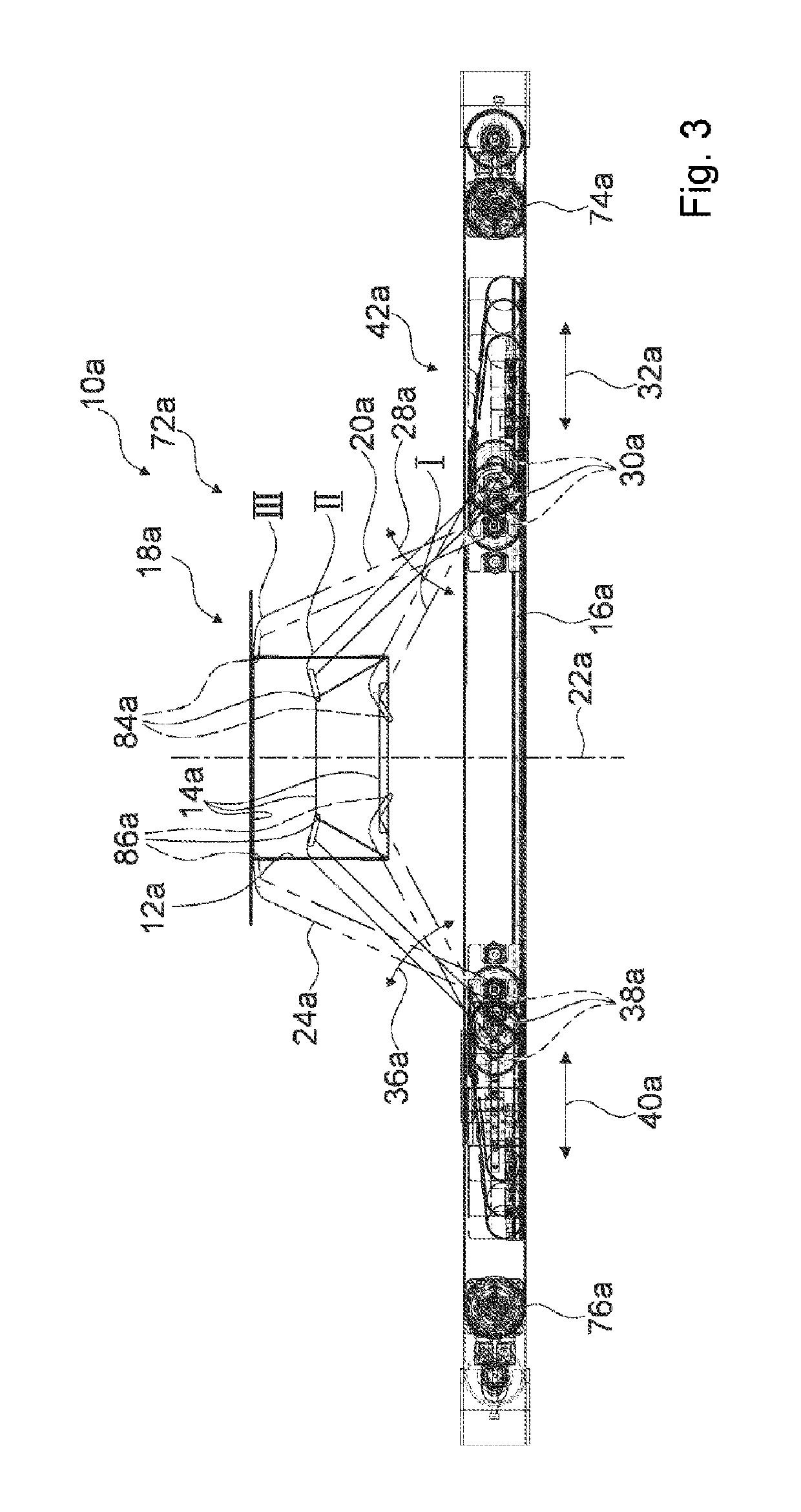
[0032]FIGS. 1 to 4 show a detail of a packaging machine 72a with a device 10a according to the invention in a first exemplary embodiment. FIG. 3 shows a schematic diagram of the kinematics of the device 10a in three different positions I to III. The device 10a serves for tensioning a tensioning element 14a of a packaging container 12a, which is realized as a rubber band.

[0033]The device 10a comprises a linear axis 16a and a pair of pivot arms 18a which includes a first pivot arm 20a and a second pivot arm 24a which, with reference to a symmetry axis 22a which is perpendicular to the linear axis 16a, is arranged in a mirror-symmetrical manner to the first pivot arm 20a. In FIG. 1 described here, the first pivot arm 20a is arranged on the right-hand side and the second pivot arm 24a is arranged on the left-hand side. This provides a convention in this description and is not to be understood as binding.

[0034]The first pivot arm 20a is mounted by way of a first pivot arm rotary bearing ...


PUM

PropertyMeasurementUnit
movementaaaaaaaaaa
displacement movementaaaaaaaaaa
displacementaaaaaaaaaa

Abstract

The invention relates to a device for processing at least one packaging container, in particular for stretching out at least one stretching element of the packaging container, comprising at least one pivoting-arm pair, which comprises a first pivoting arm and a second pivoting arm, which is arranged in a mirror-symmetric manner in relation to the first pivoting arm with respect to an axis of symmetry perpendicular to the at least one linear axis, wherein the first pivoting arm is supported in such a way that the first pivoting arm can be rotated about a first pivoting-arm axis of rotation perpendicular to the axis of symmetry in a first rotational motion and can be displaced in the direction of the at least one linear axis in a first displacement motion and the second pivoting arm is supported in such a way that the second pivoting arm can be rotated about a second pivoting-arm axis of rotation perpendicular to the axis of symmetry in a second rotational motion and can be displaced in the direction of the at least one linear axis in a second displacement motion, and comprising a coupling transmission, which is designed to produce the first rotational motion and the first displacement motion of the first pivoting arm and the second rotational motion and the second displacement motion of the second pivoting arm from at least one first driving motion and one second driving motion, and wherein the first rotational motion and the second rotational motion are synchronous to each other and in opposite directions and the first displacement motion and the second displacement motion are synchronous to each other and in opposite directions.

Description

BACKGROUND OF THE INVENTION[0001]A device for processing at least one packaging container, in particular for tensioning at least one tensioning element of the packaging container, has already been proposed. Such a packaging container with a tensioning element and a device for tensioning the tensioning element are disclosed in WO2014006398A2.SUMMARY OF THE INVENTION[0002]Proposed is a device for processing at least one packaging container, in particular for tensioning at least one tensioning element of the packaging container, having at least one linear axis, having at least one pair of pivot arms which includes a first pivot arm and a second pivot arm which is arranged in a mirror-symmetrical manner with respect to the first pivot arm with reference to a symmetry axis which is perpendicular to the at least one linear axis, wherein the first pivot arm is mounted so as to be rotatable in a first rotational movement about a first pivot arm rotational axis which is perpendicular to the ...

Claims


Application Information

Patent Timeline
Patent Type & Authority Patents(United States)
IPC IPC(8): B65B13/02B65B11/02B65D5/72B65B11/00B65D5/52
CPCB65B13/022B65B11/025B65D5/722B65B2011/002B65D5/52
Inventor SCHOLL, FRANK
Owner SYNTEGON PACKAGING SYST AG
Learn More