Electric tool changer

Pending Publication Date: 2022-01-27
GIMATIC SRL
View PDF0 Cites 0 Cited by
  • Summary
  • Abstract
  • Description
  • Claims
  • Application Information

AI Technical Summary

Benefits of technology

The present invention is an electric tool changer that is small and compact while still maintaining its performance. The design allows for a compact motor to be positioned close to the locking mechanism, while still being able to access the tools easily. The robot-side portion of the tool holder has a cup-shaped element with a male portion that is inserted into. The element has holes for the balls and a sliding control element that prevents the balls from coming out of their seats outwards. The balls are also prevented from coming inwards by making tapered seats, which allows for a part of the balls to protrude.

Problems solved by technology

The Applicant found that solutions like the one described in U.S. Pat. No. 8,132,816, with orthogonal axes, are often affected by this drawback: the electric motor protrudes laterally from the tool changer and, in general, it is difficult to produce a tool changer with orthogonal axes that has minimum side dimensions, i.e. minimum side dimensions in the direction transverse to the coupling direction of the male portion with the female portion.
This results in operational problems when the tool and the manipulator are operating in tight spaces, such as in a mold; in these cases it is desirable that the operation of the manipulator is not limited by the tool changer because of the dimensions thereof.

Method used


Image

  • Electric tool changer
  • Electric tool changer
  • Electric tool changer

Examples


Embodiment Construction

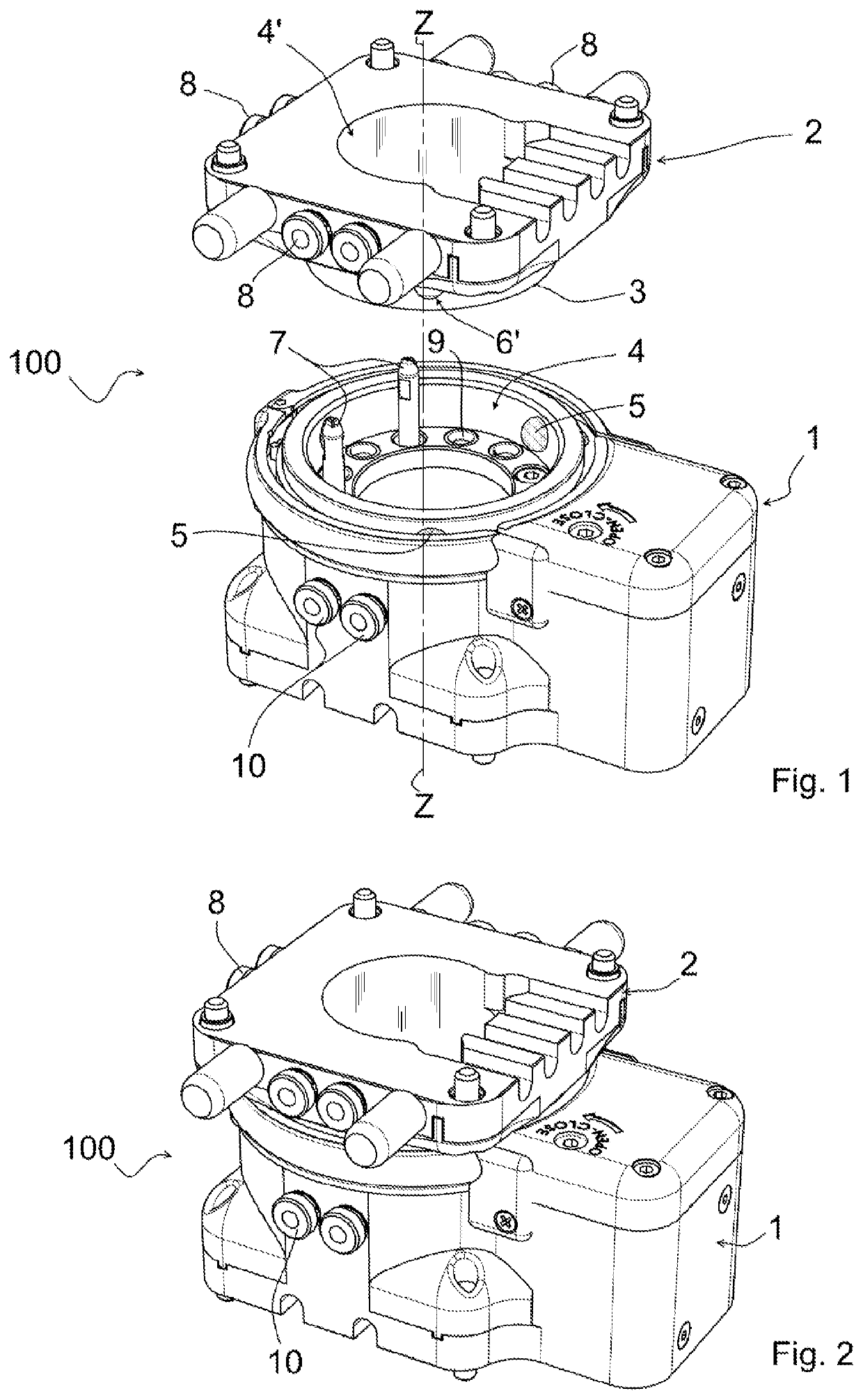
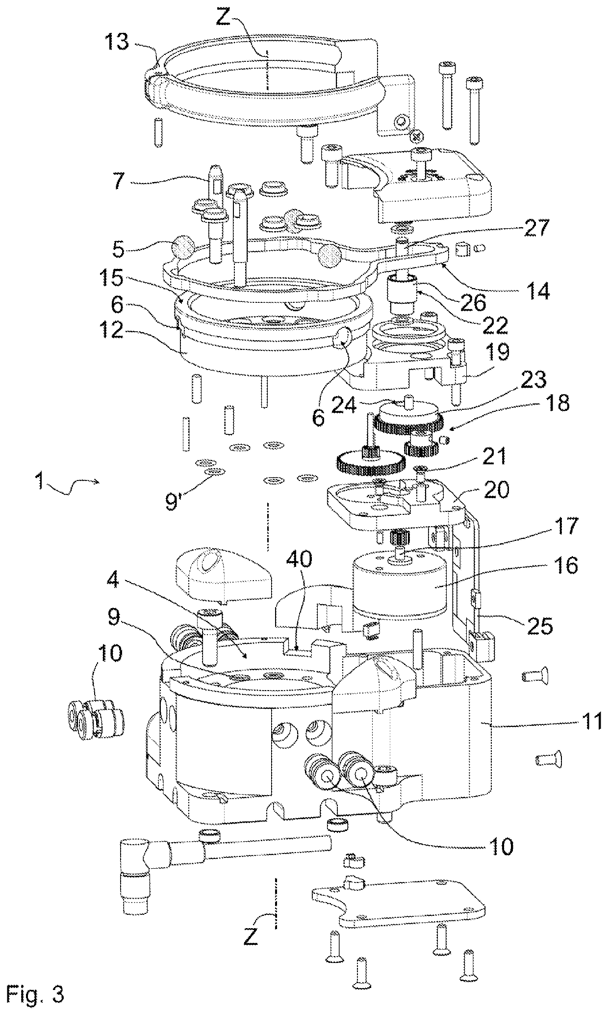
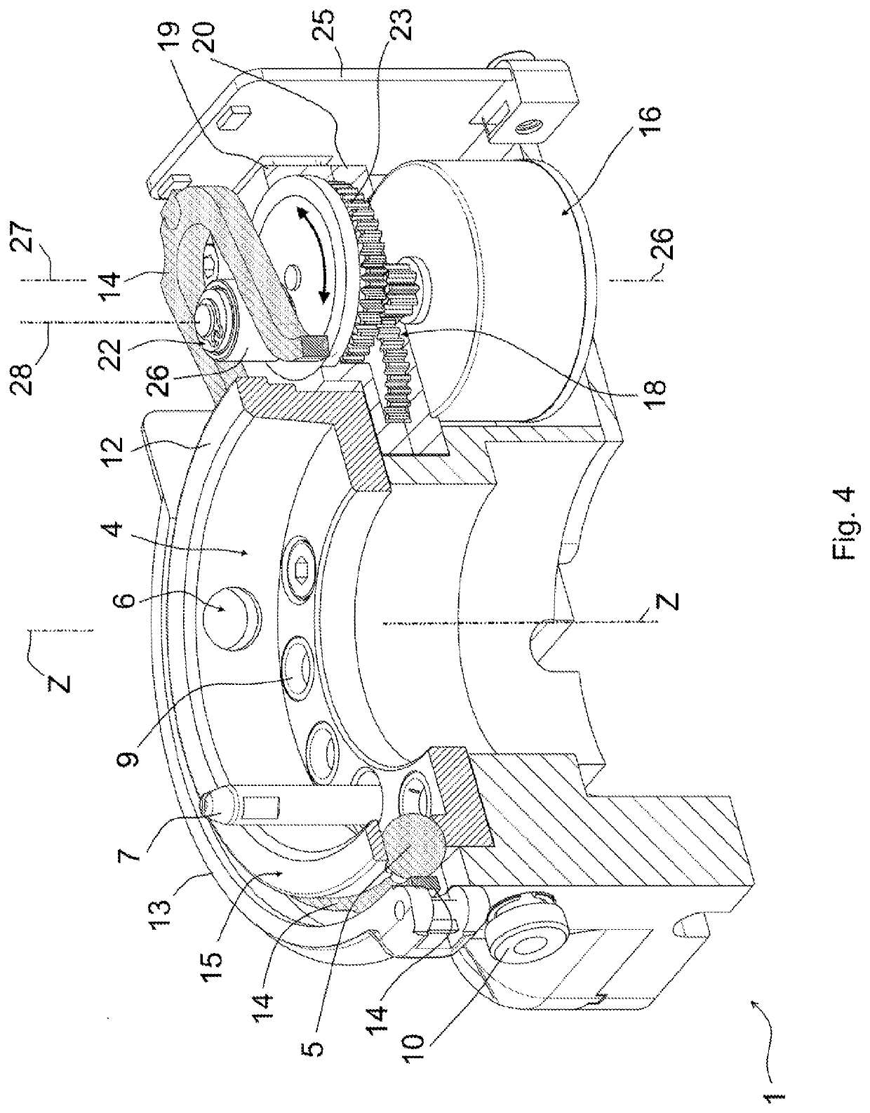
[0056]Referring to all the accompanying figures, the numeral 100 denotes a tool changer according to the present invention, comprising a robot-side portion 1 and a tool-side portion 2. The robot-side portion 1 is intended to be fixed to an industrial manipulator, e.g. a robotic arm, and the tool-side portion 2 is intended to be fixed to a tool which has to be interchangeably mounted on the manipulator, e.g. a gripper, a gripping element, tongs, a suction cup or, in general, any tool provided in the field of industrial automation EOAT.

[0057]The reference Z-Z denotes a coupling axis of the portions 1 and 2, hereafter called longitudinal axis, i.e. the axis along which the tool-side portion 2 is at least partially inserted in the robot-side portion 1. In particular, FIG. 1 shows the two portions 1 and 2 separate from each other, e.g. moving close or away, while FIG. 2 shows the two portions 1 and 2 functionally coupled to each other, corresponding to a configuration in which the tool i...


PUM


Abstract

A tool changer is described, the tool changer includes a robot-side portion having a longitudinal axis and fixable to a manipulator, and a tool-side portion fixable to a tool and abuts against the robot- side portion along the longitudinal axis. The tool changer also includes a lock to lock the tool-side portion on the robot-side portion, and an actuator of the lock. The lock is selectively movable by the actuator between a locked position, where it engages the tool-side portion that abuts against the robot-side portion, thereby preventing the separation of the two portions of the tool changer, and an unlocked position, where it does not engage the tool-side portion, which can therefore be separated from the robot- side portion. The actuator of the lock is an electric motor whose drive shaft rotates on a rotation axis parallel to the longitudinal axis.

Description

FIELD OF THE INVENTION[0001]This invention relates to an electric tool changer, in particular a tool changer for EOAT (end of arm tooling) applications that allows tools to be removably coupled to a robotic manipulator.STATE OF THE ART[0002]In the field of industrial automation, the use of tool changing devices, or more simply tool changers, is known, the tool changers allowing a robotic manipulator, for example an articulated arm, to pick up and move the tool each time required for a given machining operation.[0003]The present invention refers in particular to tool changers comprising:[0004]a so-called tool-side portion, intended to be fixed to the tool to be picked up and moved, and[0005]a so-called robot-side portion, intended to be fixed to the manipulator to integrally move with it, and designed to receive and hold the tool-side portion for the required time.[0006]Document DE 102016222506 in the name of the Applicant describes an example of tool changer of this type, electrical...

Claims


Application Information

Patent Timeline
IPC IPC(8): B25J15/04B25J19/00
CPCB25J15/0416B25J19/0033
Inventor BELLANDI, GIUSEPPE
Owner GIMATIC SRL
Why Eureka
Try Eureka