Transverse-electromagnetic (TEM) radio-frequency coil for magnetic resonance

a radio-frequency coil and transverse-electromagnetic technology, applied in the field of magnetic resonance, can solve the problems of difficult definition and specification of rf cable connections, inability to provide reliable simulation basis of such devices, and inability to supply or feed rf power in qbc-based mr systems, etc., to achieve the effect of reducing image quality, reducing z-sensitivity, and reducing sensitivity

Active Publication Date: 2019-06-18
KONINKLJIJKE PHILIPS NV
View PDF23 Cites 0 Cited by
  • Summary
  • Abstract
  • Description
  • Claims
  • Application Information

AI Technical Summary

Benefits of technology

[0007]Thus, with the present invention, the elements of a conventional or classical TEM coil are modified in such a way, that the strip section of each TEM coil element is extended laterally (e.g. azimuthally or circumferentially) at either or both of its opposite ends before connection to an RF shield or screen. Each of these extensions or additional parts of the coil elements has been found to produce field contributions that lead to reduced sensitivity along the z-axis during signal transmission and therefore to less noise pickup from regions outside the imaging field of view during signal reception. Thus, the reduced FOV in z-direction for the proposed TEM coil not only reduces noise reception from regions outside the FOV (as for a QBC) but also reduces the SAR generated in those regions during transmission. Furthermore, the proposed TEM coil generates a significant reduction in the RF-power required for generating a given B-field, which may drastically reduce costs compared to a QBC-based MR-system.
[0013]It will be appreciated by persons skilled in the art that the invention concerns a TEM coil structure, which may also be considered to include a stripline coil element or a dipole element with capacitive end loading. That is, it will be understood that different terms, such as stripline resonator or even dipole resonator (e.g. capacitively shortend) may be employed in association with the concept proposed herein. In this connection, in a preferred embodiment, dielectric material may be provided between the strip sections and the electrical ground of the shield or screen. Furthermore, dielectric material may be provided between strip sections and a subject to be imaged. The use of dielectric material between the RF shield or screen and strip conductor and / or the use of dielectric material between strip conductor and the subject to be imaged can be beneficial for shielding the electric field.
[0015]In a preferred embodiment, the lateral extensions and the strip sections have different distances to the electrical ground which helps reduce e-fields resulting from discrete capacitors either in the strip sections or the lateral extensions. The lateral extensions are preferably lowered closer to the RF shield or screen in order to reduce e-fields associated with the currents therein. Furthermore, decoupling of the individual coil elements may be achieved using any of a variety of decoupling circuits, such as capacitive, inductive, or Quarter wave line circuits.
[0019]Although conventional TEM coils typically have a larger sensitivity profile in the z-direction, which can lead to safety issues with the specific absorption rate (SAR) of RF energy by patients (particularly in the head region) and can also reduce image quality due to additional sensitivity to noise pickup, the inventive concept is able to overcome these issues. The proposed concept provides L-shaped or U-shaped TEM-type coil elements having truncated or reduced sensitivity profiles in the z-direction which resolves the problems mentioned and yet still preserves the characteristics of the TEM coil having a well-defined RF ground (i.e. via an RF shield or screen). The lateral extensions of the U-shaped TEM coil elements have been found to provide ‘ring-like’ current contributions resulting in a reduction of the z-sensitivity encountered in a conventional TEM coil. Thus, the proposed TEM coil concept incorporates circumferential or ring sections, which provide a short FOV and a defined RF ground better suited for simulations, especially in relation to SAR issues. As such, the concept provides a solid basis for a safe RF high field MR system, as safe patient management is based on a well defined RF system regarding array antenna element coupling (impedance matrix) and sensor data (pick-up coils). As such, the invention provides an advantageous alternative to the quadrature birdcage coil often employed in magnetic resonance imaging applications.

Problems solved by technology

As birdcage coils float with respect to RF ground, the supply or feed of RF power in QBC-based MR systems is problematic, however, due to hot RF connections.
Further, this problem does not provide reliable basis for EM simulation of such a device.
Particularly with degenerate birdcage coils, the RF cable connections are difficult to define and specify for simulations regarding the management of the specific absorption rate (SAR) of RF energy by patients in a MR system.

Method used


Image

  • Transverse-electromagnetic (TEM) radio-frequency coil for magnetic resonance
  • Transverse-electromagnetic (TEM) radio-frequency coil for magnetic resonance
  • Transverse-electromagnetic (TEM) radio-frequency coil for magnetic resonance

Examples


Embodiment Construction

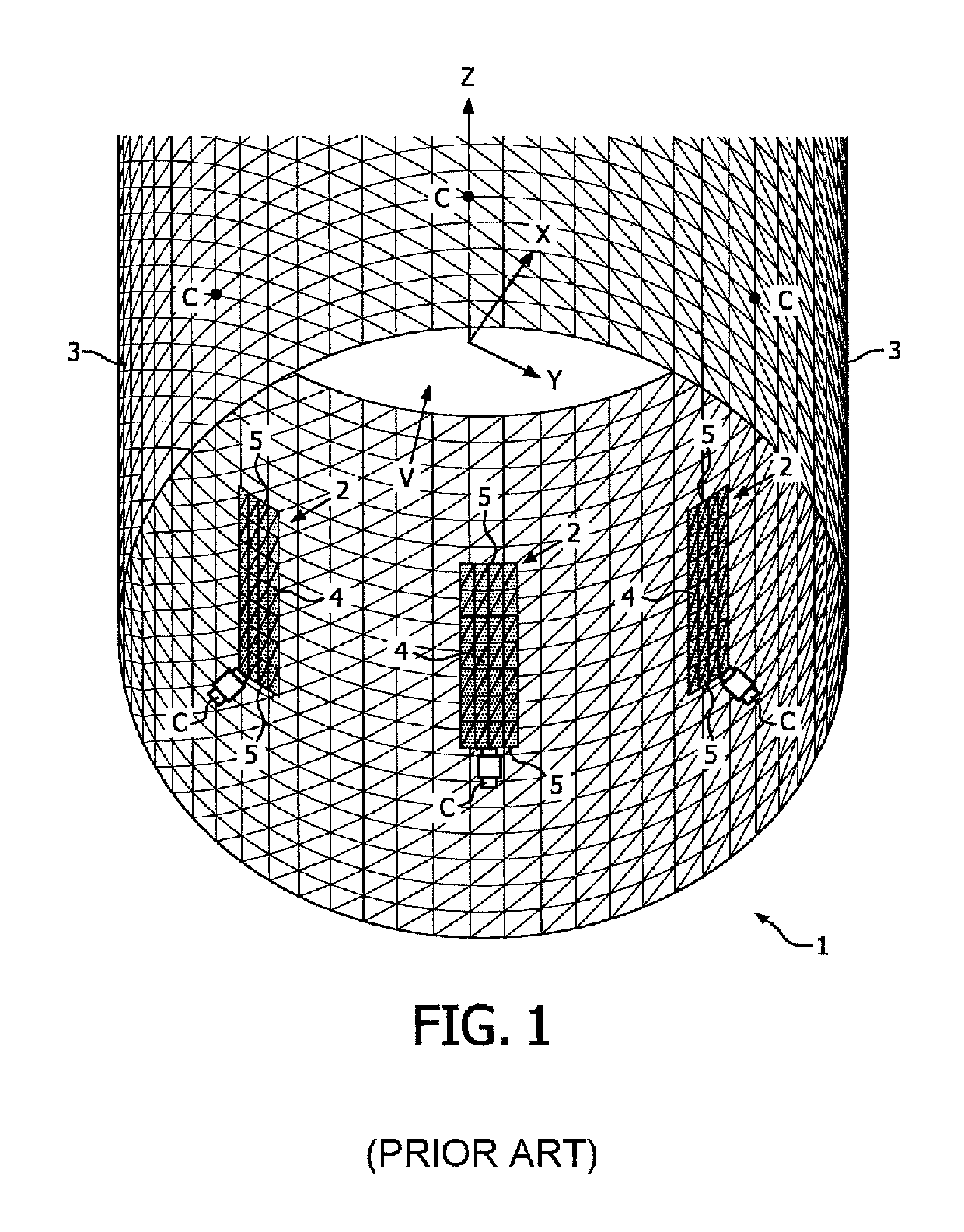
[0028]FIG. 1 shows a conventional transverse-electromagnetic (TEM) radio-frequency (RF) coil 1C for a magnetic resonance system, such as an MRI system. The conventional TEM coil 1C comprises a plurality of TEM coil elements 2 arranged within and encompassed by an RF shield 3 in the form of a cylindrical screen which functions as an RF ground for the coil 1C. A central axis of the cylindrical RF screen 3 corresponds to the z-axis of the coil 1C, as denoted by the Cartesian coordinates shown in FIG. 1. Each of the plurality of TEM coil elements 2 comprises an elongate coil strip section 4, and the TEM coil elements 2 are arranged such that the strip sections 4 are essentially parallel and spaced apart from one another at regular intervals around the z-axis inside the RF screen 3. Because the RF screen 3 in this example is circularly cylindrical, all of the strip sections 4 of the TEM coil elements 2 have basically the same radial spacing from the z-axis of the coil 1C. In this embodim...


PUM


Abstract

A transverse-electromagnetic (TEM) radio-frequency coil (1) for a magnetic resonance system, especially for a magnetic resonance imaging system, includes a coil (1) in which at least one of the opposite end regions of the elongate strip section (4) of each TEM coil element (2) has a lateral extension (6) transverse to a longitudinal extent of the strip section (4). These lateral extensions (6) combine with strip sections (4) to form L- or U-shaped TEM coil elements (2) and provide ‘ring-like’ current contributions resulting in a reduction of the z-sensitivity compared with a conventional TEM coil. The result is a coil array having TEM coil elements (2) that provide smaller sensitivity profiles in the z-direction, yet preserve the characteristics of a well-defined RF ground, e.g. via an RF shield or screen (3). The reduced field of view in z-direction not only reduces noise reception but also reduces the SAR generated in those regions during transmission.

Description

CROSS-REFERENCE TO PRIOR APPLICATIONS[0001]This application is the U.S. National Phase application under 35 U.S.C. § 371 of International Application No. PCT / IB2012 / 055308, filed on Oct. 3, 2012, which claims the benefit of U.S. Provisional Patent Application No. 61 / 545,221, filed on Oct. 10, 2011. These applications are hereby incorporated by reference herein.FIELD OF THE INVENTION[0002]The present invention relates to the field of magnetic resonance (MR), and more particularly to transverse-electromagnetic (TEM) radio-frequency (RF) coils for use in MR applications, as well as to a magnetic resonance (MR) system incorporating such coils.BACKGROUND OF THE INVENTION[0003]MR systems, and particularly magnetic resonance imaging (MRI) systems, frequently employ quadrature birdcage coils (QBCs), which have the advantage of a shorter field of view (FOV) in the z-direction (i.e. in the axial direction) while providing a higher signal-to-noise ratio (SNR) and also having lower total RF pow...

Claims


Application Information

Patent Timeline
Patent Type & Authority Patents(United States)
IPC IPC(8): G01R33/34G01R33/345
CPCG01R33/34092G01R33/34046G01R33/3453G01R33/3456
Inventor LEUSSLER, CHRISTOPHWIRTZ, DANIEL
Owner KONINKLJIJKE PHILIPS NV
Why Eureka
Try Eureka