Spiral brace

a brace and spine technology, applied in the field of braces, can solve the problems of unattractive appearance, uncomfortable wear, and complicated positioning to secure to the patient's body, and achieve the effects of less material for fabrication, more accurate position measurements, and simplified brace design and construction

Active Publication Date: 2019-06-25
3D SYST INC
View PDF32 Cites 1 Cited by
  • Summary
  • Abstract
  • Description
  • Claims
  • Application Information

AI Technical Summary

Benefits of technology

[0004]The spiral brace can be a single strip of material such as plastic that can be elastically deformed to place the brace on the limb or remove the brace from the limb. However, the brace can also be sufficiently rigid to provide any required support and immobilization of the limb. The brace can be placed on the limb by inserting a portion of the limb in an open portion of the brace so that the center axis of the brace intersects a portion of the limb. The spiral brace can be made of an elastic material and the distal and proximal portion of the brace can be elastically deformed so that the entire brace can be repositioned to wrap around the limb. Once the brace is properly positioned on the limb, the brace can allow axial rotation of the limb, but may also be rigid and strong enough to prevent bending movements of the limb. For example, if the brace is an arm brace, it may allow rotation about a center axis of the brace relative to the forearm and prevent bending of the wrist such as palmar flexion movement of the wrist and hand.
[0005]There are various features that make the brace comfortable to wear. The brace can be made of a strong plastic material having a smooth inner surface that can correspond to a digital representation of the injured limb so that the brace will provide a close, custom and personal fit for the patient's limb. Because the brace is thin it can be easily worn under clothing. The brace is also light weight and fenestrated to allow the limb to be exposed to ambient air so that perspiration from the limb can evaporate rather than being trapped by the brace. A spiral arm brace can have thickness that is between about 0.05 inch and 0.50 inch. The pitch of the spiral brace can be greater than 2 inches and less than 6 inches. The proximal portion of the brace can have a width between about 0.5 inch and 2 inches. Because the brace is thin and light weight and may look more like an ornamental object than a medical device, the patient is more likely to wear the inventive spiral brace. The brace can also include ornamental fenestration and topographical designs formed in the outer surface.
[0006]In an embodiment, the spiral brace can be used as an arm brace. The brace can have a proximal portion that fits around a forearm portion of the limb and a distal portion of the brace body fits around a hand portion of the limb. The distal hand portion of the brace can have a lower or palmar section that supports a palm of the hand portion and an upper or dorsal section that fits over a dorsum of the hand portion. This configuration can keep the spiral brace in proper alignment with the arm. Because the surface of the palm of the hand is normally concave, the inner surface of the brace body at the lower palmar section of the distal portion includes a convex surface that corresponds to the concave surface of the palm or other convex surfaces of the limb. The brace can also be configured to provide specific types of support for the hand. For example, in an embodiment, the distal limb support at the distal end of the brace may only partially surround the hand and a distal edge of the brace can be adjacent to a palmar digital crease of the hand. The distal edge of the brace may also not extend over proximal phalanx segments of the fingers so that the movement of fingers is not restricted. In an embodiment, the distal limb support of the brace does not extend over a thenar portion of the hand allowing a thumb of the hand to move freely.
[0007]If the brace is being used to prevent movement of the wrist to prevent carpal tunnel injury, the spiral brace can be wrapped in a specific manner around the arm. For example, the spiral brace can include a distal limb support that is adjacent to a palmar surface of the hand, a middle section that is adjacent to a posterior surface of the wrist and a proximal limb support at the proximal end of the brace, the proximal limb support is adjacent to an anterior surface of the forearm. If the patient attempts to move the palm in a downward motion, the downward force will cause the middle section to be pressed into the posterior surface of the wrist and the proximal limb support will be pressed into the anterior surface of the forearm. Although the brace can allow some movement, the brace functions to resist this movement to prevent injuries such as median nerve entrapment or carpal tunnel syndrome.
[0009]From the photographs, a three dimensional digital representation of the limb can be created by photogrammetry, image correlation, depth mapping or any other suitable IR and / or visible light photography based surface topography detection method. From the three dimensional representation of the limb surface topography, a spiral brace can be designed having an inner surface that corresponds to the three dimensional digital representation of the patient's limb. The measurements of the markers or markings from the photographs can be more accurate than measurements of other surface points on the patient. Because the markers can provide more accurate position measurements, the markers can be used for important design data points for the digital representation of the limb and the design of the spiral brace.
[0010]In an embodiment, the brace or cast has a smooth inner surface that conforms to the digital representation of the scanned surface of the limb and closely matches the surface measurements of the patient's body. Because the inner surface of the brace accurately conforms to the patient to provide a very close fit, the surface of the limb matches the inner surface of the brace and the brace can be worn by the patient without any padding. The brace can be made of a hard plastic material that provides structural strength to support the limb. In order to be comfortable, the inner surface of the hard plastic brace should also be very smooth. In an embodiment, the inner surface can have a surface finish of less than 500 Ra μ inch. In an embodiment, the innermost surface of the structural layer of the brace can be made of a homogeneous plastic material. In other embodiments, the entire brace can be made of a homogeneous plastic material. A brace or cast that can be worn by a patient without inner surface padding has several benefits including: simplified brace design and construction, less material for fabrication, lower weight, lower profile thickness, better ventilation, no absorption of water, easier cleaning, etc. The inner surface padding in a traditional brace can be a soft cloth that can included a compressible padded material. This inner surface padding can be completely omitted from the inventive brace.

Problems solved by technology

A problem with braces is that they can be complicated to secure to the patient's body, uncomfortable to wear and unattractive to look at.

Method used


Image

  • Spiral brace
  • Spiral brace
  • Spiral brace

Examples


Embodiment Construction

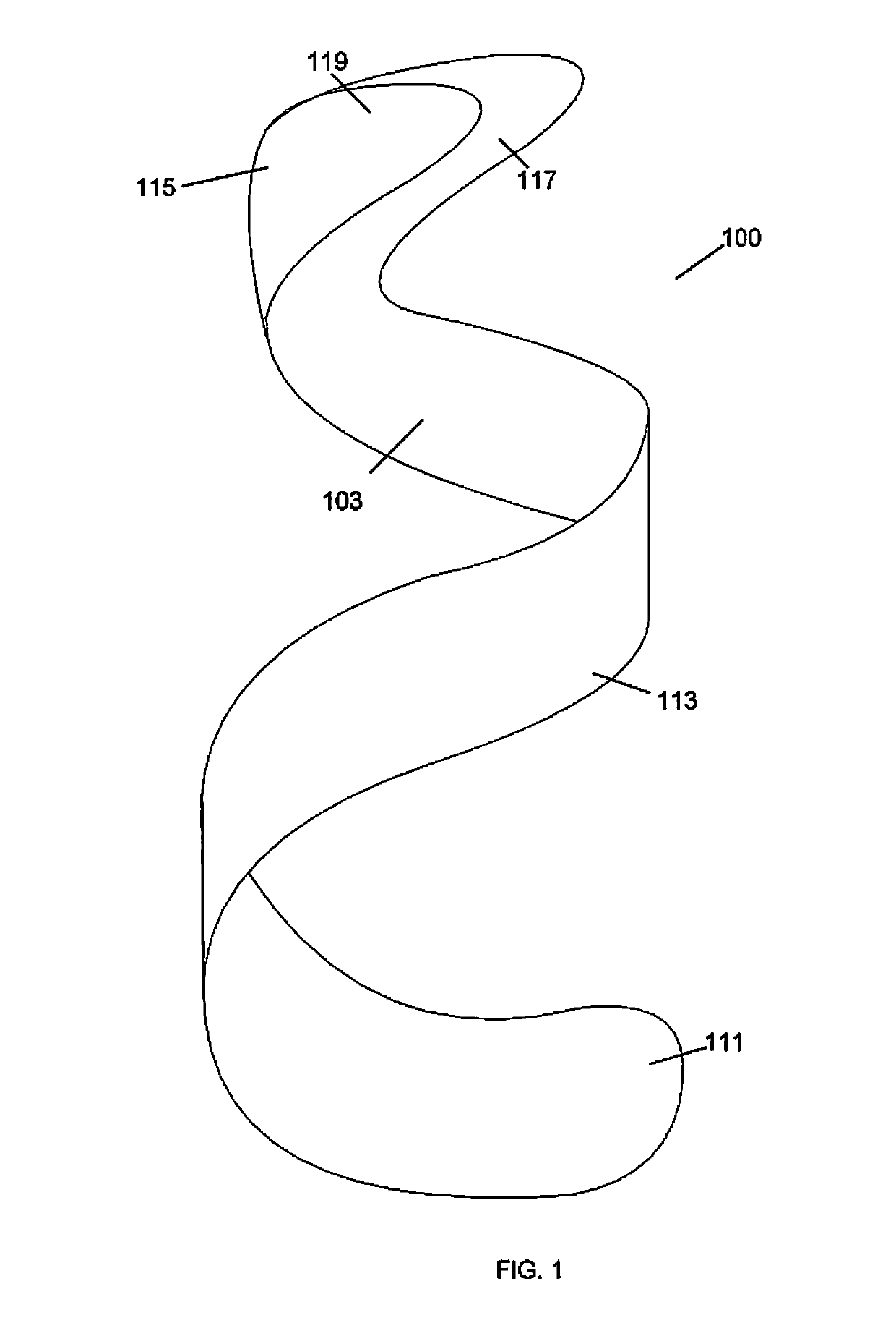
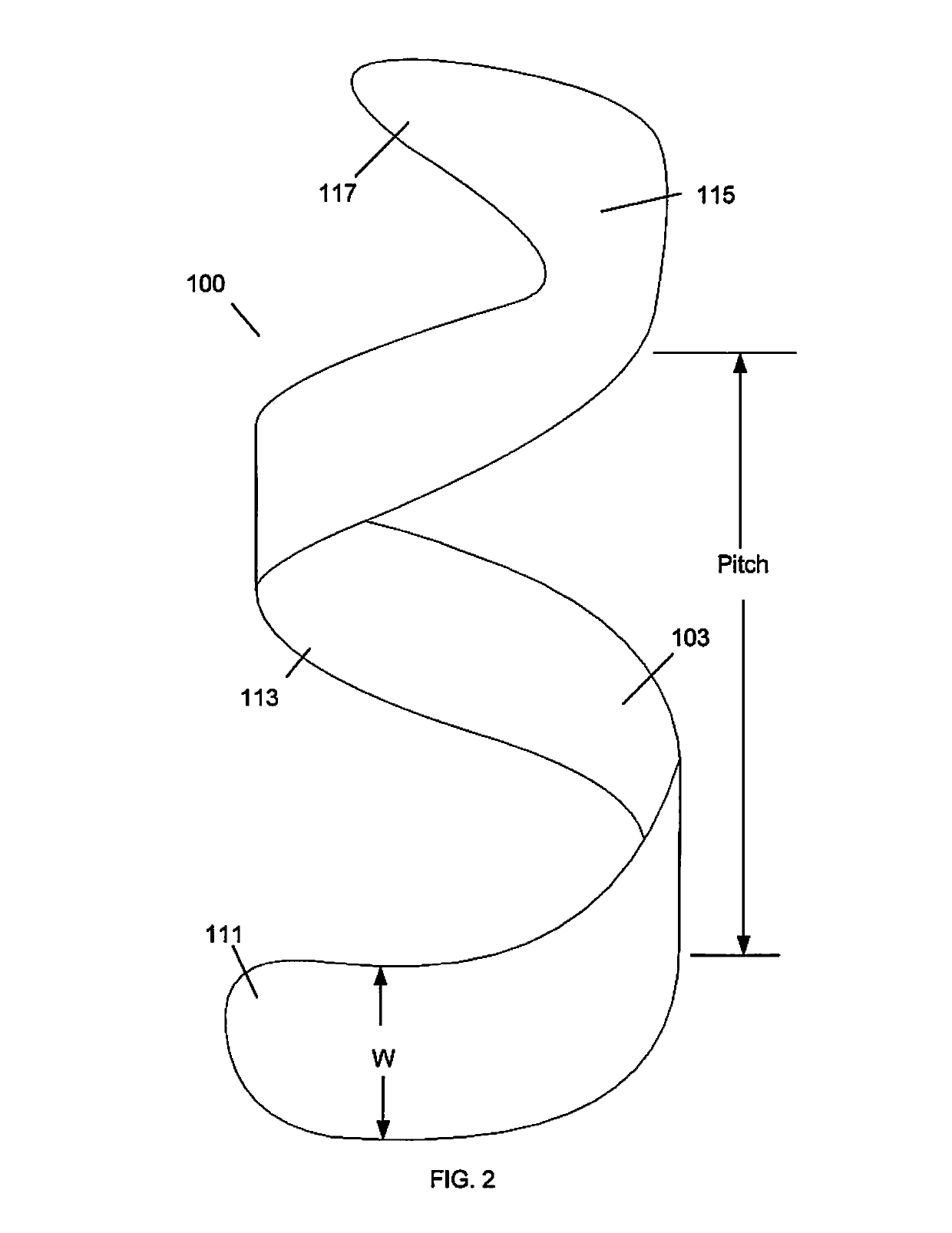
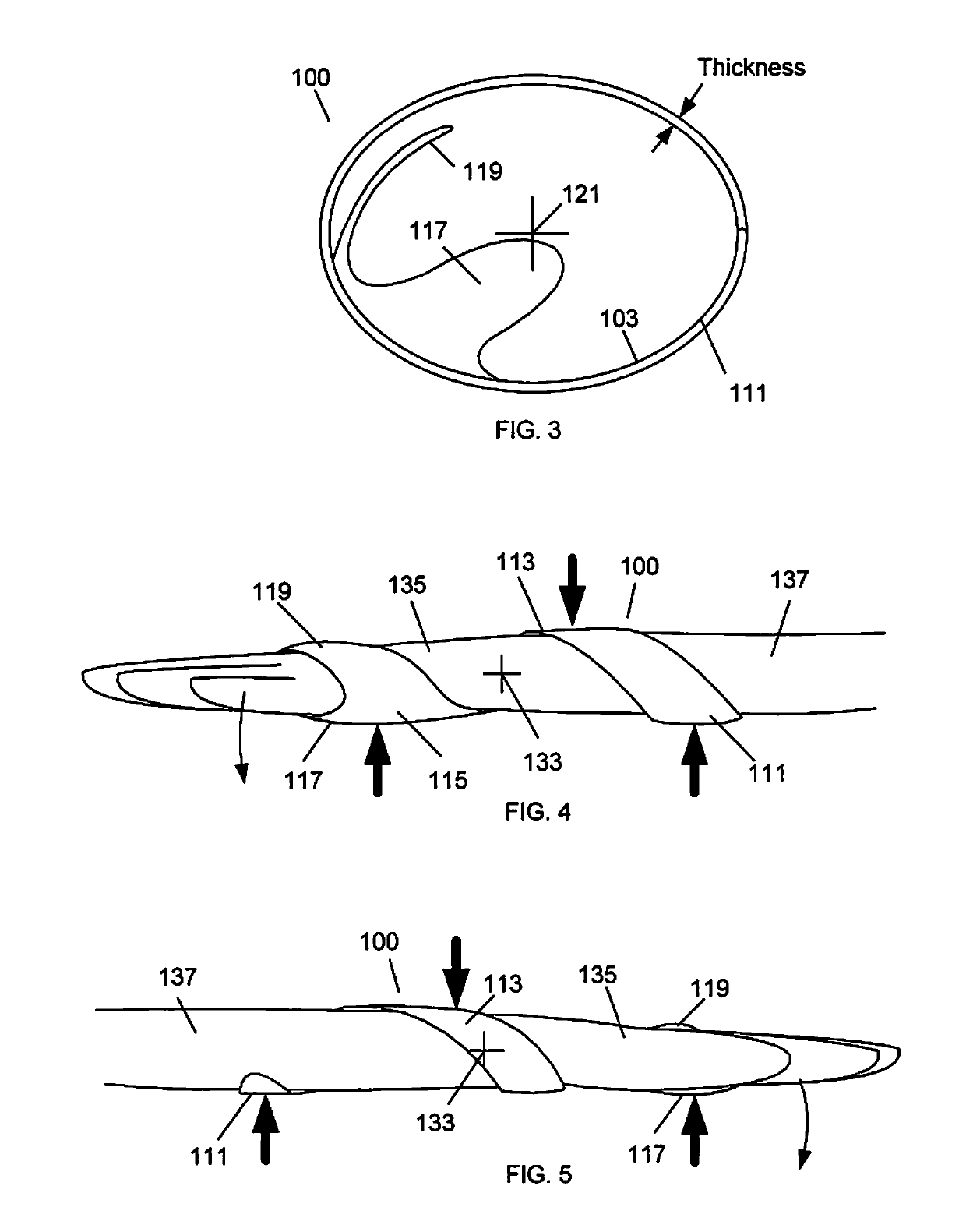
[0023]The present invention is a custom designed spiral brace. The term “spiral” is used to describe the three dimensional curve of a brace that wraps at least one full circumferential turn around an axis of the limb in a generally helical shape. The spiral brace can also have interior surfaces that correspond closely to a digital representation of a portion of a patient's body which can be from an optical scan or photograph(s) of the patient. When a patient injures a limb, the spiral brace can be designed to closely fit around the limb. In order to provide a close fit around the limb, the interior surfaces can be slightly larger than the digital representation of the portion of the patient's body. Thus, the interior surfaces are not an exact match but correspond to the digital representation of the patient's body. The inventive spiral brace can be designed to resist specific types of movement. For example, a spiral brace can be an arm brace that allows movement of the fingers and t...


PUM


Abstract

A spiral brace has an inner surface that corresponds to a digital representation of an injured limb. The spiral brace can wrap around a length of the limb in a helical manner. The body of the spiral brace may be a single piece structure that is fenestrated to provide air circulation to the injured limb.

Description

CROSS REFERENCE TO RELATED APPLICATIONS[0001]This application is a continuation-in-part of U.S. patent application Ser. No. 13 / 791,678 filed Mar. 8, 2013, which claims priority to U.S. Provisional Patent Application No. 61 / 720,861, “Spiral Brace” filed Oct. 31, 2012 and is a continuation-in-part of PCT Patent Application No. PCT / US2012 / 051612, “Adjustable Brace” filed Aug. 20, 2012 which is a continuation-in-part of U.S. patent application Ser. No. 13 / 214,096, “Adjustable Brace” filed Aug. 19, 2011, this application is also a continuation-in-part of U.S. patent application Ser. No. 14 / 255,801, “Adjustable Brace” filed Apr. 17, 2014 which is a continuation-in-part of U.S. patent application Ser. No. 13 / 214,096, “Adjustable Brace” filed Aug. 19, 2011, which is a continuation-in-part of U.S. patent application Ser. No. 12 / 820,968, “Modular Custom Braces, Casts And Devices And Methods For Designing And Fabricating” filed Jun. 22, 2010 which is a continuation-in-part of U.S. patent appli...

Claims


Application Information

Patent Timeline
Patent Type & Authority Patents(United States)
IPC IPC(8): A61F5/00A61F5/01
CPCA61F5/0118
Inventor SUMMIT, SCOTTTRAUNER, KENNETH B
Owner 3D SYST INC
Why Eureka
Try Eureka