
Gateway box convenient for heat dissipation

A gateway and convenient technology, applied in the direction of network connection, cooling/ventilation/heating transformation, electrical equipment shell/cabinet/drawer, etc., it can solve the problems of gateway box damage, difficult heat dissipation, etc., to achieve the effect of convenient disassembly

Pending Publication Date: 2021-05-14
CHENGDU HUAMAI COMM TECH
View PDF0 Cites 1 Cited by
  • Summary
  • Abstract
  • Description
  • Claims
  • Application Information

AI Technical Summary

Problems solved by technology

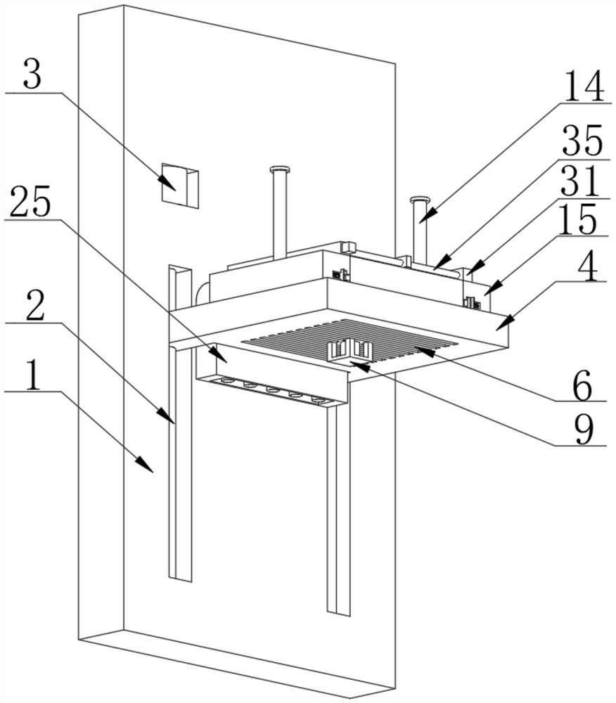
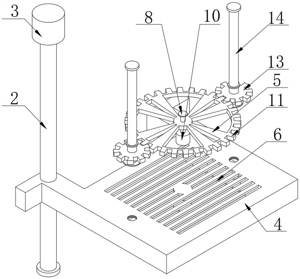
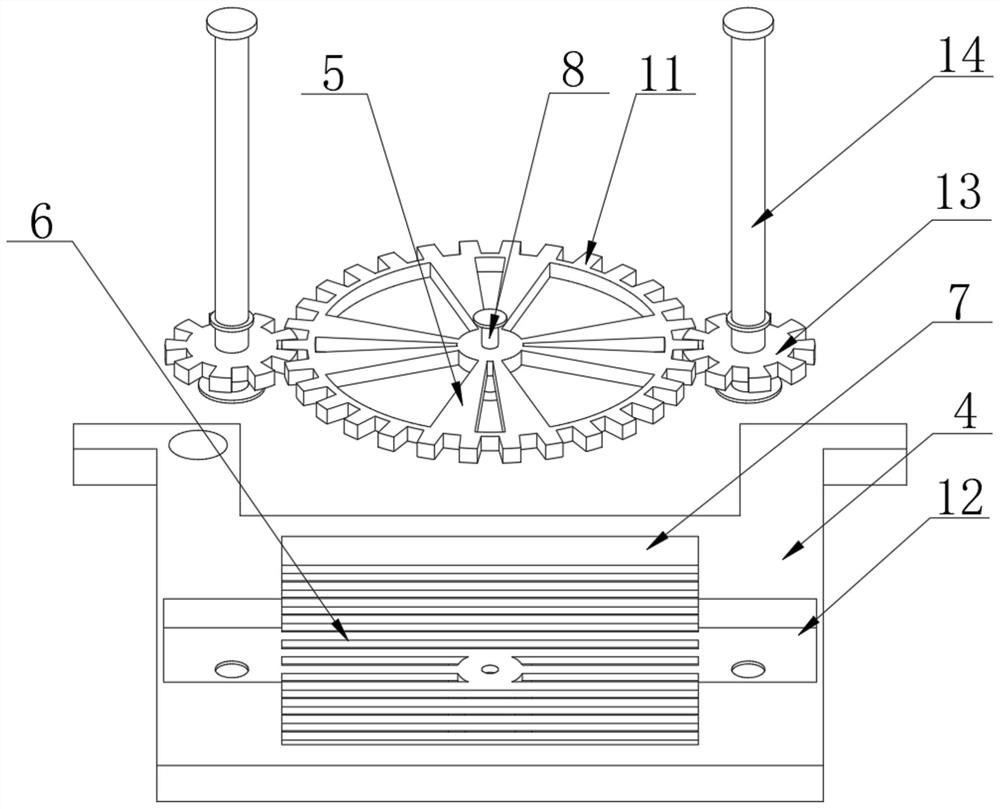
[0005] For this reason, the present invention provides a convenient gateway box for heat dissipation. The first motor drives the rotation of the connecting rod to drive the rotation of the cooling fan. Convection heat dissipation, and the meshing connection between the gear block and the tooth block plate fixedly connected to the outer side of the cooling fan and the two ends of the bearing plate can effectively drive the rotation of the two gear blocks, thereby driving the two first reciprocating wires The rotation of the bar can effectively drive the gateway box to move up and down through the threaded connection between the fixed sleeve and the first reciprocating lead screw and the sliding connection between the gateway box body and the fixed sleeve, and then move the gateway box to make the gateway box The up and down movement of the body drives the flow of air and generates wind, thereby dissipating heat from the gateway box body, so as to solve the problem that the existing gateway box is installed at the corner, and the heat generated during work is not easy to dissipate, which may easily cause the temperature of the parts inside the gateway box to be too high This leads to the problem of damage to the gateway box

Method used


Image

  • Gateway box convenient for heat dissipation
  • Gateway box convenient for heat dissipation
  • Gateway box convenient for heat dissipation

Examples


Embodiment 1

[0031] Refer to attached Figure 1-6 , a convenient heat dissipation gateway box provided by the present invention includes a wall 1, a first sliding groove is opened at both ends of one side of the wall 1, and a first threaded rod 2 is arranged inside the first sliding groove, The first threaded rod 2 is arranged inside the first slide groove and is connected to the wall 1 in rotation. A placement groove is opened on one side of the wall body 1, and a first motor 3 is fixedly connected to the inside of the placement groove. One end of a threaded rod 2 is fixedly connected to the output end of the first motor 3, and the outer side of the first threaded rod 2 is threadedly connected with a bearing plate 4, and the bearing plate 4 is arranged inside the first sliding groove and is slidably connected with the wall body 1, The inner side of the bearing plate 4 is provided with a heat dissipation mechanism;

[0032] The heat dissipation mechanism includes a heat dissipation fan 5,...

Embodiment 2

[0042] Refer to attached Figure 7-8, a convenient gateway box for heat dissipation provided by the present invention, a fixed block 31 is fixedly connected to the top of the fixed sleeve 15, a third motor 32 is fixedly connected to one side of the fixed block 31, and a Inside the inner groove, a rotating rod 33 is arranged inside the inner groove, and the rotating rod 33 is arranged inside the inner groove and is connected to the fixed block 31 in rotation, and one end of the rotating rod 33 is fixedly connected to the output end of the third motor 32, and the Both ends of the outer sides of the rotating rod 33 are fixedly connected with a first bevel gear 34, and the rotation of the rotating rod 33 is driven by the third motor 32 to drive the meshing connection between the first bevel gear 34 and the second bevel gear 36;

[0043] Both ends of one side of the fixed block 31 are provided with a second rotating hole, and a second reciprocating screw 35 is arranged inside the s...


PUM


Abstract

The invention discloses a gateway box convenient for heat dissipation. According to the technical scheme, the gateway box comprises a wall body, first sliding grooves are formed in the two ends of one side of the wall body, first threaded rods are arranged in the first sliding grooves, a placement groove is formed in one side of the wall body, the outer sides of the first threaded rods are in threaded connection with a bearing plate, and a heat dissipation mechanism is arranged on the inner side of the bearing plate. The heat dissipation mechanism comprises a heat dissipation fan, heat dissipation holes are formed in the two sides of the bearing plate, a first inner cavity is formed in the bearing plate, a first rotating hole is formed in the bottom of the bearing plate, a connecting rod is arranged in the first rotating hole, and the connecting rod is rotationally connected with the bearing plate. The heat dissipation fan is arranged in the first inner cavity and fixedly connected with the outer side of the connecting rod. The gateway box convenient for heat dissipation has the beneficial effects that the problem that an existing gateway box is installed at a wall corner, heat generated during working is not easy to dissipate, the temperature of parts in the gateway box is easy to be too high, and the gateway box is damaged is solved.

Description

technical field [0001] The invention relates to the technical field of communication gateway boxes, in particular to a gateway box that facilitates heat dissipation. Background technique [0002] A gateway is also called a network connector or a protocol converter. The gateway realizes network interconnection above the network layer. It is a complex network interconnection device. It is only used for the interconnection of two networks with different high-level protocols. Even, it can also be used for LAN interconnection. A gateway is a computer system or device that acts as a conversion task. It is used between two systems with different communication protocols, data formats or languages, or even completely different architectures. A gateway is a Translator. [0003] The prior art has the following deficiencies: most of the installations of the existing gateway boxes are directly placed at the place connected with the optical fiber lines, and since most of the installation...

Claims


Application Information

Patent Timeline
Patent Type & Authority Applications(China)
IPC IPC(8): H05K7/20H02K7/116H02K7/06H05K7/14H05K5/02H04L12/66
CPCH02K7/06H02K7/116H04L12/66H05K5/0204H05K5/0213H05K5/0217H05K5/0247H05K7/1401H05K7/20172
Inventor 杨大方李聪
Owner CHENGDU HUAMAI COMM TECH
Learn More