Mug with a hollow pumping piece

a technology of mugs and pumping pieces, applied in the field of mugs, can solve the problems of increasing the manufacturing cost of mugs a lot, requiring both hands, and requiring a lot of stirring, so as to achieve the effect of simple and less expensive manufacturing

Active Publication Date: 2019-06-25
LAARMANN ELMAR +6
View PDF9 Cites 0 Cited by
  • Summary
  • Abstract
  • Description
  • Claims
  • Application Information

AI Technical Summary

Benefits of technology

[0005]The aim of the invention is to introduce a novel mug which is simpler and less expensive to manufacture than before and in which the beverage can be simultaneously stirred by the same hand in which the mug is held, by means of a pumping device in the mug.
[0007]The mug according to the invention has the advantage that the mug, based on a pumping device in connection with the mug, which pumping device can be used simultaneously by the same hand in which the mug is held, can be made more efficient in stirring the beverage and simpler in its structure and less expensive in its manufacturing costs than mugs of prior art where the stirring of the beverage is based on a pumping device in the mug.

Problems solved by technology

A drawback in this conventional way of stirring the beverage is that both hands are always needed for doing it when the cup is held in hand.
However, there are situations in which one hand is needed for something else than holding the cup or stirring the beverage in it simultaneously when drinking from the cup or holding the cup in hand.
As a result, the flows causing stirring are primarily air bubbles, wherein liquid flows causing actual stirring remain relatively insignificant and inefficient.
Moreover, the arrangement for stirring comprises several separate elements which increases the manufacturing costs of the mug a lot compared with a conventional mug.

Method used


Image

  • Mug with a hollow pumping piece
  • Mug with a hollow pumping piece
  • Mug with a hollow pumping piece

Examples


Embodiment Construction

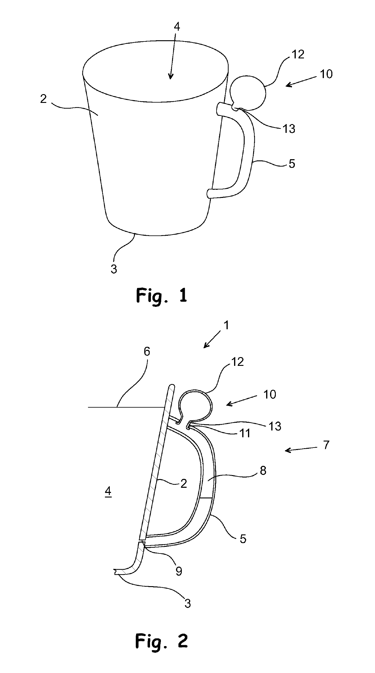
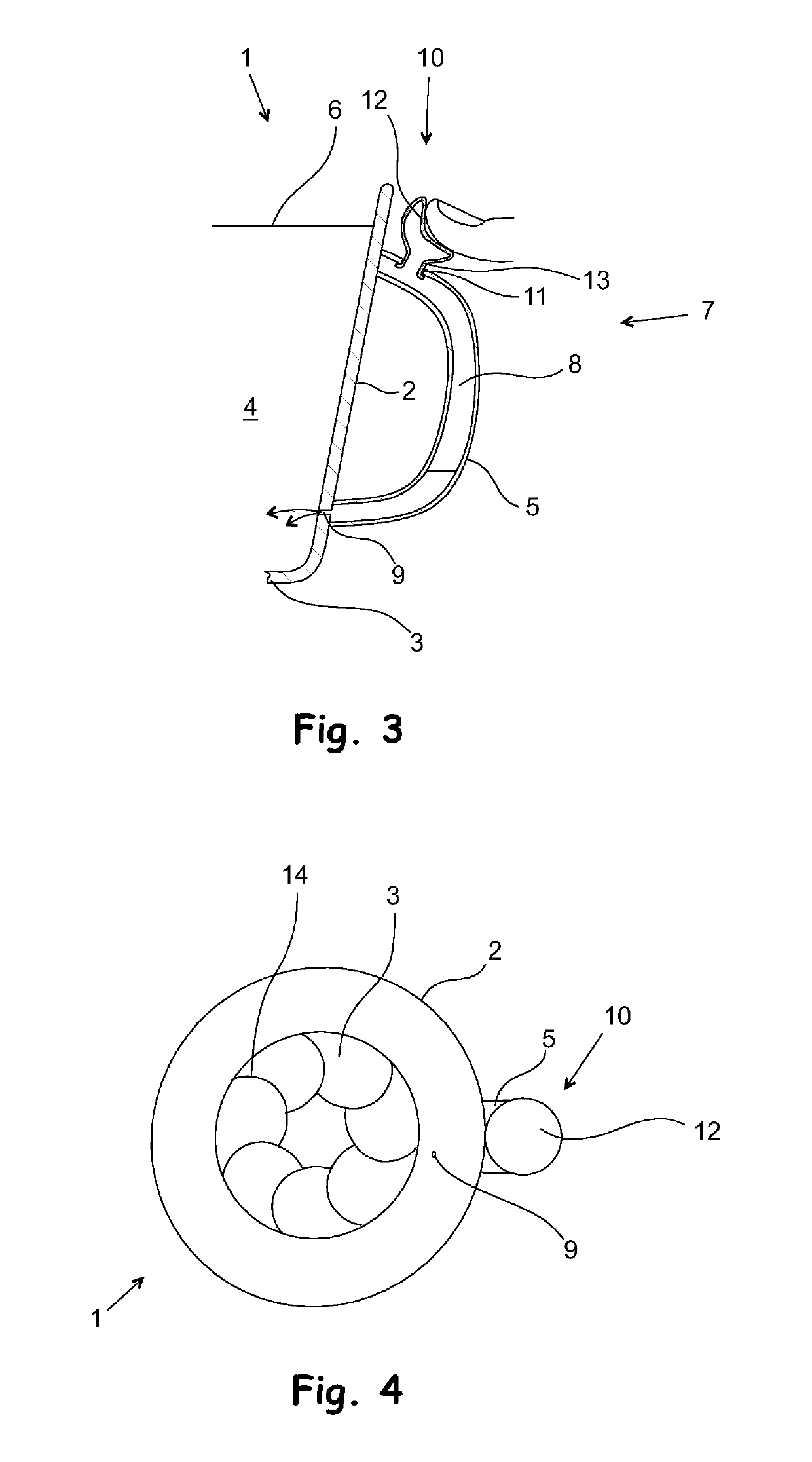
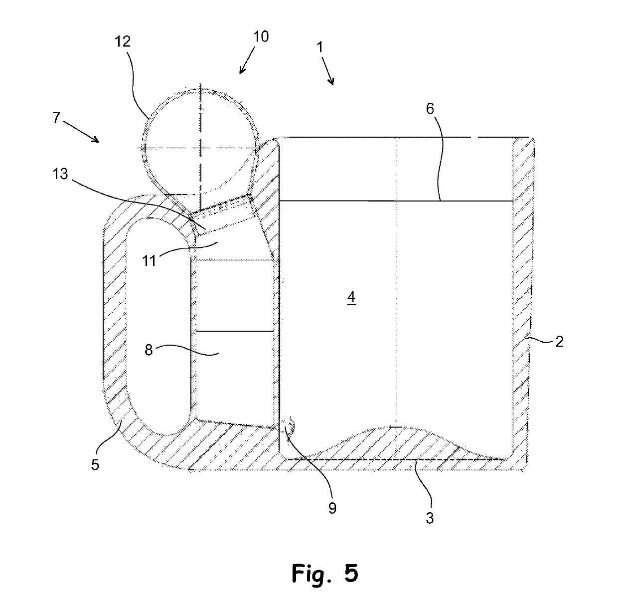
[0014]FIGS. 1 to 4 show a mug 1 according to the invention. In this embodiment, the mug 1 has a circular cross-section; in other words, it comprises a cylindrical side wall 2 and a bottom 3 connected to the lower edge of the side wall. Delimited by the side wall 2 and the bottom 3, a liquid space 4 is formed inside them, into which space a beverage 6 to be drunk from the mug is poured when the mug 1 is used. However, the shape of the side walls and the bottom of the mug according to the invention may vary; in other words, its cross-sectional shape can also be different from circular, such as oval or angular.

[0015]In this case, the mug 1 is made by casting from a suitable castable material, such as clay, porcellaine or plastic. A handle 5 is connected to the side wall 2 of the mug 1, for gripping the mug 1 when drinking the beverage 6 from it. In this case, the handle 5 is integrated in the mug 1, but the handle 5 could be a separate piece as well.

[0016]The mug 1 according to FIGS. 1...


PUM


Abstract

A mug including a stirring unit connected to the liquid space of the mug, for stirring a beverage contained in the liquid space of the mug simultaneously by the same hand in which the mug is held, and in which mug the stirring unit includes a pumping space separate from the liquid space, and a pumping device connected to the pumping space, configured to increase and to decrease the pressure of air inside the pumping space in an alternating manner. In the mug according to the invention, a flow channel extends from the pumping space to the liquid space, enabling the flow of the beverage contained in the liquid space from the liquid space to the pumping space and from the pumping space to the liquid space, whereby a liquid flow can be formed in the flow channel, for stirring the beverage in the liquid space by the pumping device.

Description

FIELD[0001]The invention relates to a mug.BACKGROUND[0002]Conventionally, for stirring a beverage in a beverage cup, such as a cup of coffee or a cup of tea, a separate stirring means is used, such as a teaspoon or, in the case of disposable cups, sometimes also e.g. a wooden stick.[0003]A drawback in this conventional way of stirring the beverage is that both hands are always needed for doing it when the cup is held in hand. However, there are situations in which one hand is needed for something else than holding the cup or stirring the beverage in it simultaneously when drinking from the cup or holding the cup in hand. A need for keeping one hand free during drinking the beverage in the cup or holding the cup in hand occurs, for example, when driving a car or when holding another object or piece relating to drinking the beverage, such as another piece of tableware (e.g. a saucer) or a foodstuff (e.g. a slice of bread, a bun, a cookie, or the like).[0004]At present, mugs and other ...

Claims


Application Information

Patent Timeline
Patent Type & Authority Patents(United States)
IPC IPC(8): B01F15/00A47G19/22B01F13/00B01F11/00B01F5/00A47J43/27B01F25/10B01F31/65B01F33/501B01F35/32B01F35/53
CPCB01F15/00506A47G19/2205A47J43/27B01F15/00876B01F11/0074B01F13/002B01F5/0065B01F25/103B01F31/651B01F33/5011B01F35/3202B01F35/53A47G19/22B65D37/00B01F35/00
Inventor LAARMANN, ELMARDENISOFF, ALEKSANDERINNO, MARKOKALDOJA, KAURUSIN, JALVARUSIN, RAIDOKALEV, ARDO
Owner LAARMANN ELMAR
Why Eureka
Try Eureka