
Relating to textiles incorporating electronic devices

a technology of electronic devices and textiles, applied in the field of textile incorporation of electronic devices into textiles, can solve the problems of damage to conductive devices, gaps between packaging fibers and also between fibers that form the retaining sleeve, and are associated with such yarns

Active Publication Date: 2021-03-23
ADETEXS LTD
View PDF45 Cites 1 Cited by
  • Summary
  • Abstract
  • Description
  • Claims
  • Application Information

AI Technical Summary

Benefits of technology

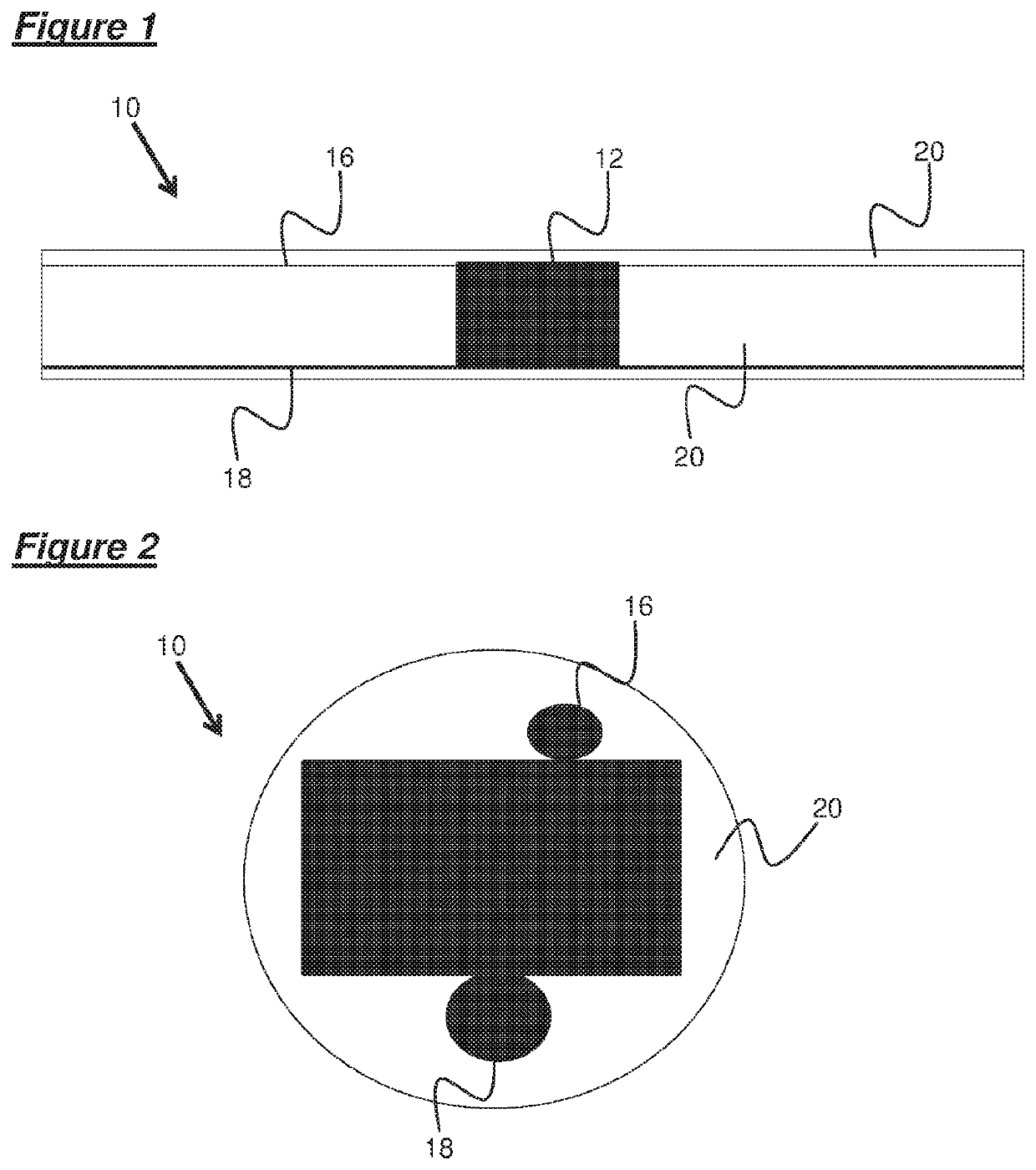
The present invention provides a fiber that can be used as an electronic device and an electrical conductor. The fiber is encapsulated by a unitary body of at least one material, which protects the electronic device and the electrical conductor from external environments. The unitary body may be formed by a single material or a combination of materials. The fiber may have a cross-sectional area of constant size or shape between its first and second free ends. The fiber may also have a region of increased cross-sectional area in the region of the electronic device, which provides increased structural rigidity and resistance to heat / pressure. The fiber may be fixed to a reinforcing member, such as a wire, prior to encapsulation. The fiber may be wound around the reinforcing member, for example in a helical fashion, which allows for expansion of the electrical conductor without causing deformation. The technical effects of the invention include improved protection of the electronic device and electrical conductor, simplified manufacturing process, and improved signal transmission.

Problems solved by technology

This may result in the conductive devices being exposed to the external environment, and may result in damage to the conductive devices.
Although the yarn of GB 2529900 provides an electronically functional yarn which can be incorporated into a garment, there are nevertheless disadvantages associated with such yarn.
In particular, when the yarn is bent, gaps can appear between packaging fibers and also between the fibers that form the retaining sleeve.
This may result in the conductive interconnects that extend between electronic devices being exposed to the external environment, and may result in damage to the conductive interconnects.
Furthermore, the presence of packaging fibers and a retaining sleeve can interfere with the function performed by the electronic device.

Method used


Image

  • Relating to textiles incorporating electronic devices
  • Relating to textiles incorporating electronic devices
  • Relating to textiles incorporating electronic devices

Examples


second embodiment

[0075]a fiber according to embodiments of the present invention, generally designated 100, is shown schematically in FIG. 8.

[0076]The fiber 100 comprises an electronic device 102, first 104 and second 106 electrical conductors, a reinforcing thread 108, a resin body 110, and first 112 and second 114 electrical connectors.

[0077]The electronic device 102 may be any appropriate electronic device, but in the present case is a temperature sensor 12. The first 104 and second 106 electrical conductors are formed from copper wire, and are electrically connected to the first 112 and second 114 electrical connectors of the temperature sensor 102. The first 104 and second 106 electrical conductors extend across the entire length of the fiber 100, as shown in FIG. 8.

[0078]The reinforcing thread 108 extends across the entire length of the fiber 100, as shown in FIG. 8. The reinforcing thread 108 may be formed of any material sufficient to reinforce the fiber 100, and in the present case is forme...

fourth embodiment

[0081]a fiber according to embodiments of the present invention, generally designated 300, is shown schematically in FIG. 10.

[0082]The fiber 300 comprises an electronic device 302, first 304 and second 306 electrical conductors, a reinforcing thread 308, and first 310, second 312, third 314, and fourth 316 resin bodies.

[0083]The electronic device 302 in the fourth embodiment is an RFID tag. The first 304 and second 306 electrical conductors are formed from copper wire, and are electrically connected to the RFID tag 302. The first 304 and second 306 electrical conductors extend across the entire length of the fiber 300, as shown in FIG. 10.

[0084]The reinforcing thread 308 extends across the entire length of the fiber 300, as shown in FIG. 10. The reinforcing thread 308 may be formed of any material sufficient to reinforce the fiber 300, and in the present case is formed from nylon.

[0085]The first resin body 310 is formed of epoxy resin and encapsulates the RFID tag 302, along with po...


PUM

PropertyMeasurementUnit
diameteraaaaaaaaaa
thermal conductivityaaaaaaaaaa
lengthaaaaaaaaaa

Abstract

A fiber for incorporation into a textile has an electronic device, and an electrical conductor connected to the electronic device is provided. The electrical conductor extends along a longitudinal axis of the fiber, and the electronic device and the electrical conductor are encapsulated by a unitary body of at least a first material.

Description

CROSS-REFERENCE TO RELATED APPLICATIONS[0001]This application claims priority to PCT Application No. PCT / GB2017 / 050980, having a filing date of Apr. 7, 2017, based on GB Application No. 1605925.5, having a filing date of Apr. 7, 2016, the entire contents both of which are hereby incorporated by reference.FIELD OF TECHNOLOGY[0002]The following relates to incorporation of electronic devices into textiles.BACKGROUND[0003]Fabric is typically woven or knitted using yarn, which is commonly formed from twisted fibers of materials such as wool or nylon. It has previously been proposed to utilise yarns which incorporate electronic devices.[0004]An example of such a yarn is disclosed in US 2009 / 139,198. The yarn of US 2009 / 139,198 comprises electronic components housed in resin, with conductive devices twisted around the resin to form the outer surface of the yarn. This may result in the conductive devices being exposed to the external environment, and may result in damage to the conductive d...

Claims


Application Information

Patent Timeline
Patent Type & Authority Patents(United States)
IPC IPC(8): D02G3/44D02G3/12D02G3/36
CPCD02G3/441D02G3/12D02G3/36D10B2401/18
Inventor RATHNAYAKE, ANURA SARATHCHANDRA
Owner ADETEXS LTD
Learn More