Windscreen wiper device

a technology of windscreen wiper and connecting device, which is applied in vehicle maintenance, vehicle cleaning, transportation and packaging, etc., can solve the problems of increasing design cost and manufacturing cost, and achieve the effect of improving the force transfer

Active Publication Date: 2019-06-25
TRICO PROD CORP
View PDF25 Cites 0 Cited by
  • Summary
  • Abstract
  • Description
  • Claims
  • Application Information

AI Technical Summary

Benefits of technology

[0004]The two-piece construction of the base allows the pieces to be made of different materials from one another, thereby allowing each piece to be made of a material that is ideal for its purpose. For example, the first piece can be made of a plastic material that can be ultrasonically welded with the at least one longitudinal strip, and the second piece can be made of metal which is more resistant to deformation during operation of the wiper device.
[0007]According to still another aspect of the present invention, the protrusions have different shapes. This ensures that the second piece of the base can only be installed onto the first piece in one direction or orientation, thereby improving manufacturing consistency of the wiper device.
[0009]According to yet a further aspect of the present invention, the first piece of the base has a top surface with a plurality of bumps that are spaced from one another, and the second piece has a plurality of recesses that receive the bumps of the first piece. The bumps / recesses connection allows for improved transfer of forces between the first and second pieces of the base during operation of the wiper device.

Problems solved by technology

This leads to increased design costs since a windscreen wiper device manufacturer must design and test differently configured connecting devices for attachment with the various shapes and sizes of oscillating arm and increased manufacturing costs because different components must be manufactured to attach the same type of wiper blade with the oscillating wiper arms of different vehicles.

Method used


Image

  • Windscreen wiper device
  • Windscreen wiper device
  • Windscreen wiper device

Examples


Embodiment Construction

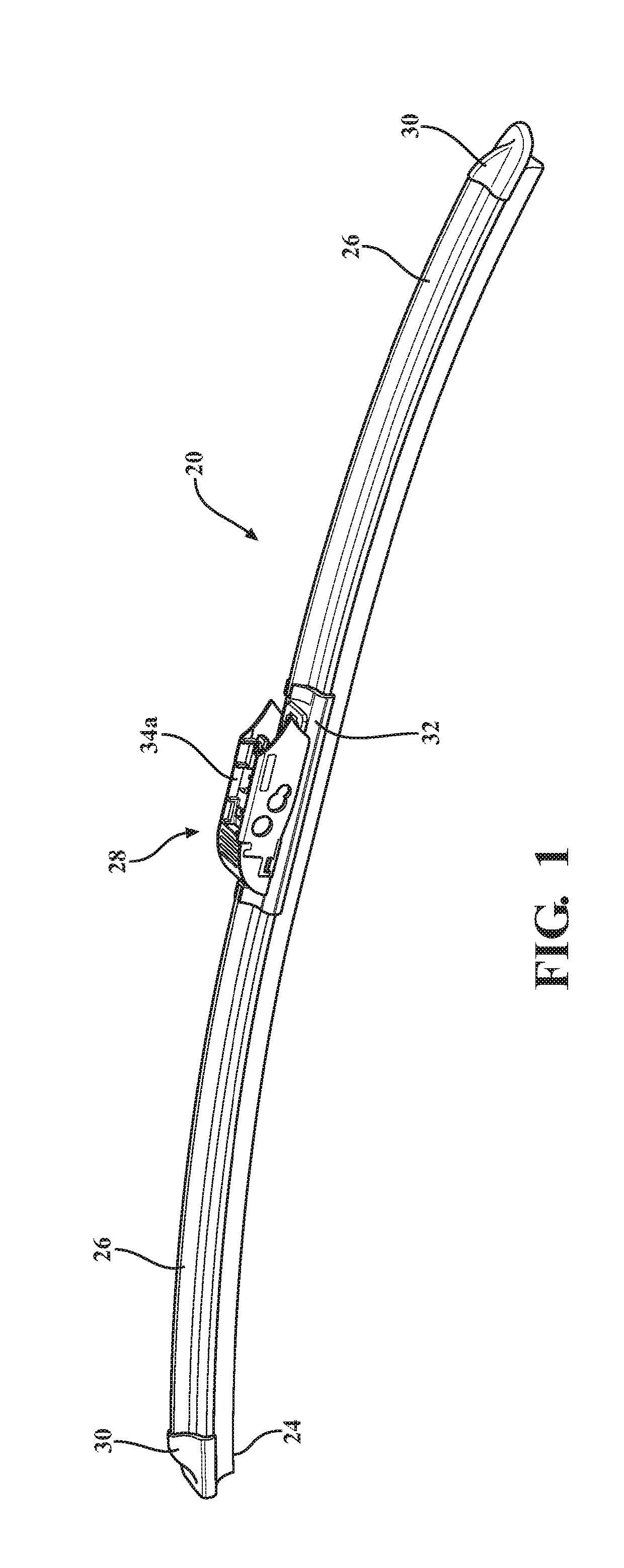
[0030]Referring to the Figures, wherein like numerals indicate corresponding parts throughout the several views, an exemplary embodiment of a windscreen wiper device 20 is generally shown in FIG. 1. The windscreen wiper device 20 has a beam-style construction in that it includes a carrier element 22 (shown in FIG. 4) which extends lengthwise in a longitudinal direction and is pre-shaped to bias a wiper strip 24 made of an elastomeric material, such as rubber, into a curved shape. The curved shape of the wiper strip 24 allows its entire length to be sealed and remain sealed against a curved windshield (not shown) of a vehicle as the windscreen wiper device 20 oscillates back and forth across the windshield. That is, in the exemplary windscreen wiper device 20, the carrier element 22, not a series of yokes, distributes a force from an oscillating wiper arm across the length of the wiper strip 24.

[0031]The exemplary windscreen wiper device 20 also includes a pair of sub-spoilers 26, wh...


PUM


Abstract

The wiper device includes a wiper blade which extends in a longitudinal direction and at least one longitudinal strip that is pre-curved to have a curved shape when in a relaxed condition. The wiper device supports the wiper blade and biases the wiper blade into a curved shape. A connecting device is attached with the at least one longitudinal strip. The connecting device includes a two-piece base and a joint part which is pivotably connected with the two-piece base. The two-piece base includes a first piece, which is directly secured with the at least one longitudinal strip, and a second piece with laterally spaced apart side walls that are each J-shaped.

Description

BACKGROUND OF THE INVENTION1. Field of the Invention[0001]The present invention is related, generally, to windscreen wiper devices and more particularly to the connecting devices of windscreen wiper devices.2. Related Art[0002]Passenger vehicles are manufactured with a range of different styles of oscillating wiper arms including, for example, various sizes of pin-style wiper arms, bayonet-style wiper arms and top lock-style wiper arms. These oscillating arms are of such different shapes and configurations that they must be secured with windscreen wiper devices in very different manners. This leads to increased design costs since a windscreen wiper device manufacturer must design and test differently configured connecting devices for attachment with the various shapes and sizes of oscillating arm and increased manufacturing costs because different components must be manufactured to attach the same type of wiper blade with the oscillating wiper arms of different vehicles.SUMMARY OF T...

Claims


Application Information

Patent Timeline
Patent Type & Authority Patents(United States)
IPC IPC(8): B60S1/38B60S1/40
CPCB60S1/4016B60S1/386B60S1/3849B60S1/3855B60S2001/4054B60S1/4038B60S2001/4022B60S2001/4035B60S2001/4051B60S1/3868B60S1/387
Inventor COX, DENNIS E.YEE, JESUSREYES, DAVID
Owner TRICO PROD CORP
Why Eureka
Try Eureka