LIDAR based 3-D imaging with structured light and integrated illumination and detection

a structured light, 3-d imaging technology, applied in the direction of measuring devices, using reradiation, instruments, etc., can solve the problems of reducing the density of point clouds, affecting the accuracy of optical design, so as to achieve systemic delays

Active Publication Date: 2019-06-25
VELODYNE LIDAR USA INC
View PDF24 Cites 23 Cited by
  • Summary
  • Abstract
  • Description
  • Claims
  • Application Information

AI Technical Summary

Benefits of technology

[0016]In another aspect, the illumination light is directed toward a particular location in the surrounding environment by one or more optical phase modulation devices (e.g., optical phase modulation device) of the LIDAR measurement system. Similarly, the return measurement light is directed onto the corresponding photodetector by the one or more optical phase modulation devices of the LIDAR measurement system. The optical phase modulation device is disposed in the optical path between the integrated LIDAR measurement device and the environment under measurement. The optical phase modulation device effectively expands the field of view and increases the sampling density within the field of view of the 3-D LIDAR system.
[0022]In another further aspect, the time of flight is determined based on the time elapsed between the detection of a detected pulse due to internal cross-talk between the illumination source and photodetector and a valid return pulse. In this manner, systematic delays are eliminated from the estimation of time of flight.

Problems solved by technology

The number of pixels such devices can generate per unit time is inherently limited due limitations on the pulse repetition rate of a single laser.
Any alteration of the beam path, whether it is by mirror, prism, or actuation of the device that achieves a larger coverage area comes at a cost of decreased point cloud density.
This leads to opto-mechanical design complexity and alignment difficulty.
In addition, mechanical devices employed to scan the illumination beams in different directions may be sensitive to mechanical vibrations, inertial forces, and general environmental conditions.
Without proper design these mechanical devices may degrade leading to loss of performance or failure.

Method used


Image

  • LIDAR based 3-D imaging with structured light and integrated illumination and detection
  • LIDAR based 3-D imaging with structured light and integrated illumination and detection
  • LIDAR based 3-D imaging with structured light and integrated illumination and detection

Examples


Embodiment Construction

[0038]Reference will now be made in detail to background examples and some embodiments of the invention, examples of which are illustrated in the accompanying drawings.

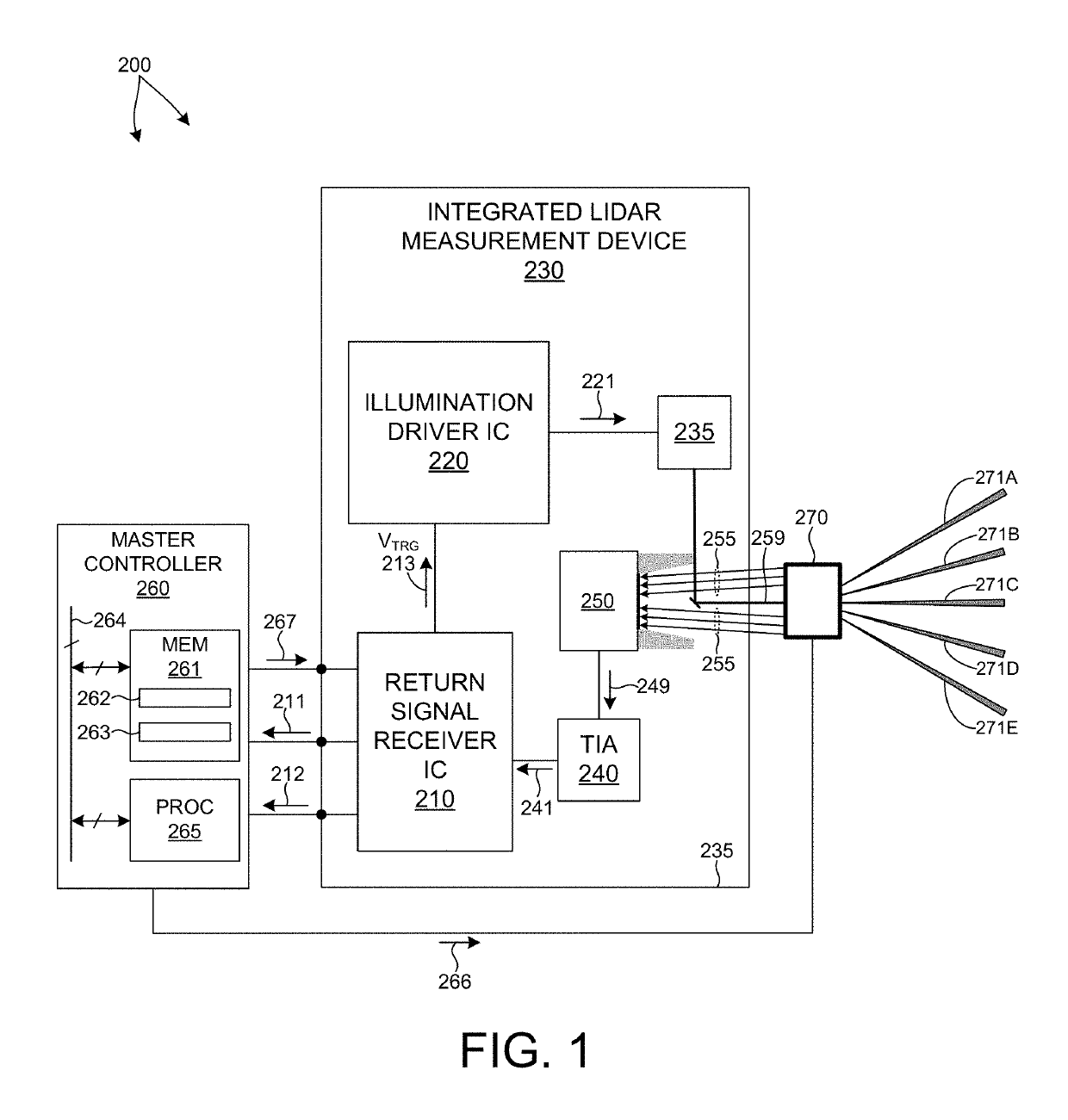
[0039]FIG. 1 depicts an LIDAR measurement system 200 in one embodiment. LIDAR measurement system 200 includes a master controller 260 and one or more integrated LIDAR measurement devices 230. An integrated LIDAR measurement device 230 includes a return signal receiver integrated circuit (IC) 210, an illumination driver integrated circuit (IC) 220, an illumination source 235, a photodetector assembly 250, and a trans-impedance amplifier (TIA) 240. Each of these elements is mounted to a common substrate 235 (e.g., printed circuit board) that provides mechanical support and electrical connectivity among the elements.

[0040]Illumination source 235 emits a measurement pulse of illumination light 259 in response to a pulse of electrical current 221. In some embodiments, the illumination source 235 is laser based (e.g., laser...


PUM


Abstract

Methods and systems for performing three dimensional LIDAR measurements with multiple illumination beams scanned over a three dimensional environment by one or more optical phase modulation devices are described herein. In one aspect, illumination light from each LIDAR measurement channel is emitted to the surrounding environment in a different direction by an optical phase modulation device. The optical phase modulation device also directs each amount of return measurement light onto a corresponding photodetector. The illumination pulse output of each LIDAR measurement channel is synchronized with commanded changes of state of each corresponding optical phase modulation device. In some embodiments, each optical phase modulation device is associated with a single LIDAR measurement channel. In some embodiments, multiple LIDAR measurement channels are associated with a single modulation device. In some embodiments, a one dimensional optical phase modulation device is employed. In other embodiments, a two dimensional optical phase modulation device is employed.

Description

CROSS REFERENCE TO RELATED APPLICATION[0001]The present application for patent claims priority under 35 U.S.C. § 119 from U.S. provisional patent application Ser. No. 62 / 473,628, entitled “LIDAR Based 3-D Imaging With Structured Light And Integrated Illumination And Detection,” filed Mar. 20, 2017, the subject matter of which is incorporated herein by reference in its entirety.TECHNICAL FIELD[0002]The described embodiments relate to LIDAR based 3-D point cloud measuring systems.BACKGROUND INFORMATION[0003]LIDAR systems employ pulses of light to measure distance to an object based on the time of flight (TOF) of each pulse of light. A pulse of light emitted from a light source of a LIDAR system interacts with a distal object. A portion of the light reflects from the object and returns to a detector of the LIDAR system. Based on the time elapsed between emission of the pulse of light and detection of the returned pulse of light, a distance is estimated. In some examples, pulses of ligh...

Claims


Application Information

Patent Timeline
Patent Type & Authority Patents(United States)
IPC IPC(8): G01S7/48G01S7/486G01S17/42G01S17/10G01S7/481G01S17/89G01S7/4861
CPCG01S7/4861G01S7/4811G01S7/4816G01S17/10G01S17/42G01S17/89G01S7/4817G01S7/4815
Inventor HALL, DAVID S.REKOW, MATHEW NOEL
Owner VELODYNE LIDAR USA INC
Why Eureka
Try Eureka