Laundry device

a technology for washing machines and sinks, which is applied in the direction of washing machines with receptacles, other washing machines, paper towels, etc., can solve the problems of radial vibration and relieve the vibration between the inner tub and the outer tub, and achieve the effect of relieving vibration and easy shaking

Active Publication Date: 2019-07-02
QINGDAO HAIER SMART TECH R & D CO LTD
View PDF13 Cites 0 Cited by
  • Summary
  • Abstract
  • Description
  • Claims
  • Application Information

AI Technical Summary

Benefits of technology

[0007]To this end, an object of the present invention is to provide a laundry device that is capable of suppressing the vibration of an inner tub and / or an outer tub in a radial direction, with the aim of overcoming at least one of the drawbacks in the prior art by.
[0034]Further, the laundry device of the present invention can utilize the magnetic repulsion between the upper magnetic ring and the inner magnetic ring to allow the forces of gravity of the inner tub and the contents therein to be directly applied to the bottom wall of the outer tub, thereby reducing the forces applied to the rotary sleeve for connecting the inner tub and the rotating mechanism, which can prevent fatigue failure of the rotary sleeve and prolong the service life of thereof so as to reduce the cost of the laundry device on the one hand; and on the other hand, can also reduce the force applied to the rotating mechanism via the rotary sleeve, i.e., reducing the burden on the rotating mechanism to prevent the occurrence of damage thereto, and reducing the cost of maintenance of the laundry device.

Problems solved by technology

At the same time, the inventors of the present application found that the prior art technical solution of suspending the inner tub in the outer tub can only relieve the vibration between the inner tub and the outer tub in the vertical direction (i.e., in the axial direction of the inner and outer tubs).
However, the inventors of the present application further recognize that in the case of a pulsator washing machine, during rotation of the inner tub in a horizontal plane about a rotary shaft thereof in the vertical direction, the inner tub easily shakes due to eccentricity and thereby causes the radial vibration.

Method used


Image

  • Laundry device
  • Laundry device
  • Laundry device

Examples


Embodiment Construction

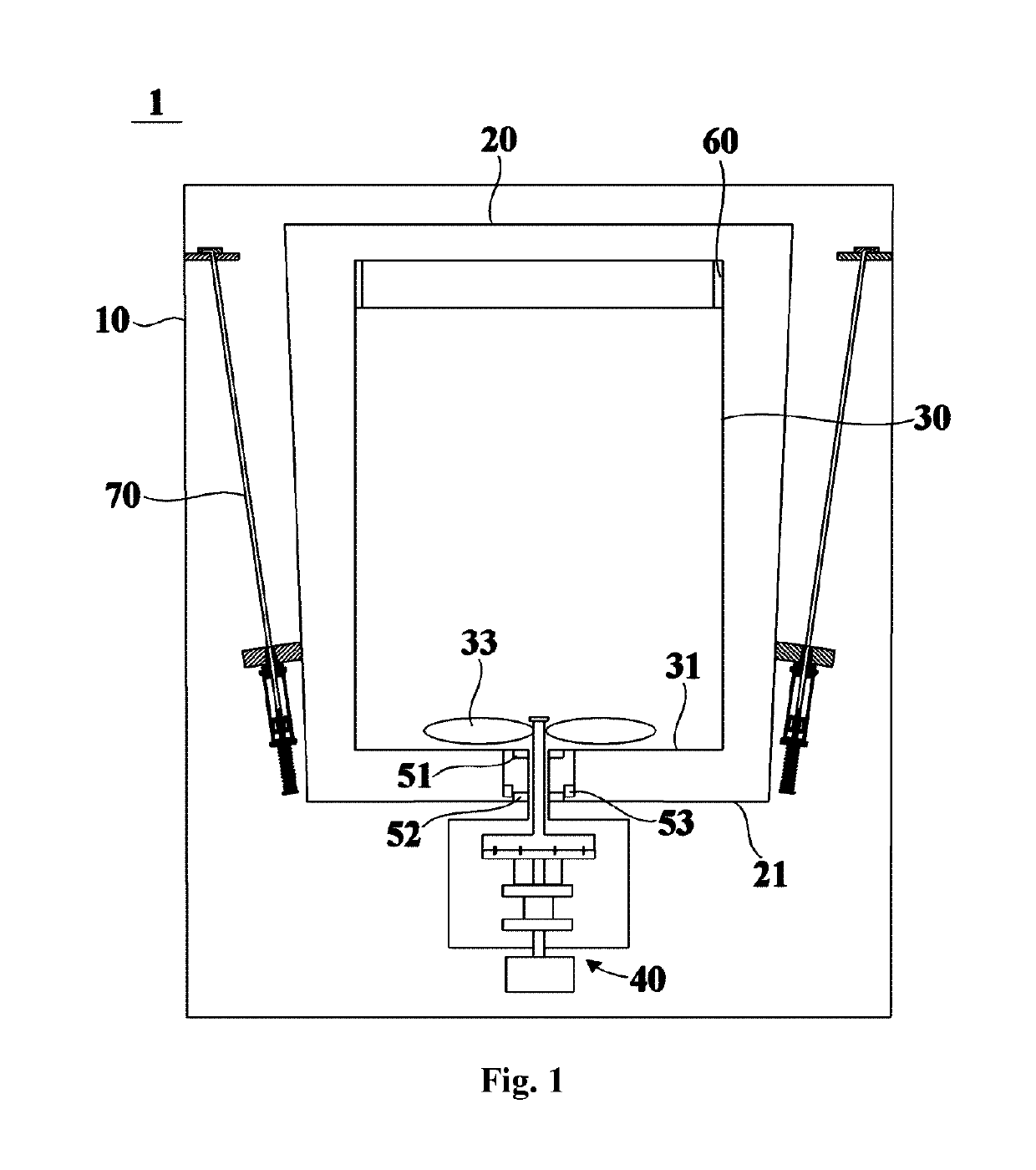
[0044]FIG. 1 is a schematic structural diagram of a laundry device 1 according to an embodiment of the present invention. The laundry device 1 may comprise an outer tub 20, and an inner tub 30 rotatably arranged in the outer tub 20. Further, the laundry device 1 further comprises a housing 10 forming the overall appearance of the laundry device, a plurality of damping suspension rods 70 for suspending the outer tub 20 in the housing 10, and a balancing ring 60 arranged at the top of the inner tub 30 to weaken the vibration of the inner tub 30. The laundry device 1 may be a radial rotating laundry device with the inner tub 30 thereof being rotated in a horizontal plane about a rotary shaft extending in the vertical direction. In particular, the laundry device 1 may be a pulsator washing machine, and a pulsator 33 for agitating the laundry in the washing process is arranged in the inner tub 30.

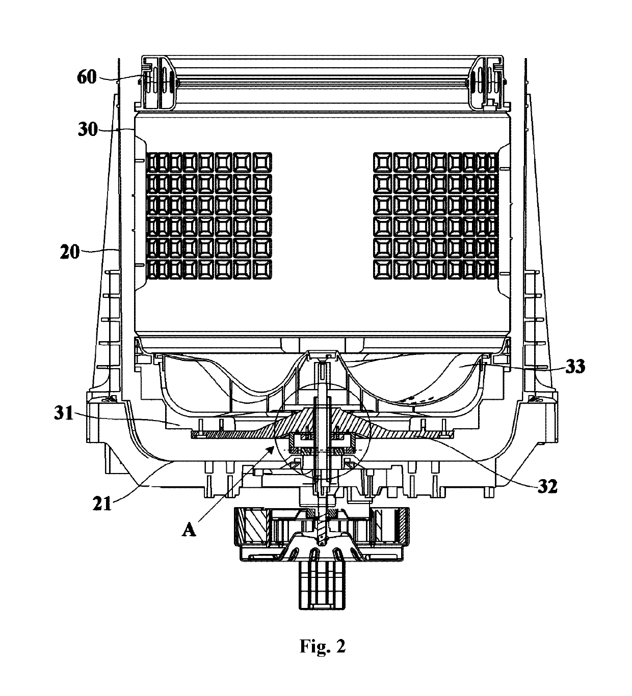
[0045]FIG. 2 is a schematic sectional diagram of a laundry device 1 in an idle state accordi...


PUM


Abstract

A laundry device comprises an outer tub, an inner tub, an inner magnetic ring and an outer magnetic ring. One of the inner magnetic ring and the outer magnetic ring is directly or indirectly fixed on a bottom wall of the inner tub and positioned at the outer side of the bottom wall of the inner tub, and the other one is directly or indirectly fixed on a bottom wall of the outer tub and positioned at the inner side of the bottom wall of the outer tub. An upper end face and a lower end face of the inner magnetic ring have the same polarity as the upper end face and the lower end face of the outer magnetic ring so that a radial repulsion between the inner magnetic ring and the outer magnetic ring is used to suppress vibration of the inner tub and / or the outer tub.

Description

CROSS-REFERENCE TO RELATED APPLICATIONS[0001]This application is a national phase entry of International Application No. PCT / CN2016 / 112439, filed Dec. 27, 2016, which claims priority to Chinese Application No. 201511004283.8, filed Dec. 28, 2015, the entire contents of which are incorporated herein by reference.CROSS-REFERENCE TO RELATED APPLICATIONS[0002]This application is a national phase entry of International Application No. PCT / CN2016 / 112439, filed Dec. 27, 2016, which claims priority of Chinese Application No. 201511004283.8, filed Dec. 28, 2015, the entire contents of which are incorporated herein by reference.TECHNICAL FIELD[0003]The present invention relates to a household appliance, in particular to a laundry device.BACKGROUND OF THE INVENTION[0004]At present, for the common pulsator washing machines in the market, a number of (generally four) suspension rod systems are used to fixedly suspend an outer tub in a housing of the washing machine, and an inner tub is rotatably...

Claims


Application Information

Patent Timeline
Patent Type & Authority Patents(United States)
IPC IPC(8): D06F37/24D06F37/26D06F37/12D06F37/30D06F39/00D06F23/04
CPCD06F37/24D06F37/12D06F37/268D06F39/00D06F37/269D06F37/30D06F23/04D06F37/40
Inventor YIN, XIANGWU, FENGLINGMOU, QIUQILAO, CHUNFENGZHANG, JIANGTAO
Owner QINGDAO HAIER SMART TECH R & D CO LTD
Why Eureka
Try Eureka