Ultrasonic meter

a technology of ultrasonic meters and meter heads, applied in the direction of fluid speed measurement, measuring devices, instruments, etc., can solve the problems of inability to reduce the width of the groove too much, limited groove depth, etc., and achieve the effect of improving flow guidan

Active Publication Date: 2019-07-02
DIEHL METERING
View PDF11 Cites 0 Cited by
  • Summary
  • Abstract
  • Description
  • Claims
  • Application Information

AI Technical Summary

Benefits of technology

[0007]According to the invention, a measuring tube, the side wall of which has a plurality of grooves in the circumferential direction with raised regions between them, is used instead of a measuring tube that has a substantially circular flow cross section, for example. The grooves can be trapeziform or the inner surface of the side wall can have a trapezium profile. It is also possible for edges in a profile of this kind to be rounded. The profile of the inner surface can also be undulating. It has been recognized that a corresponding shape of the side wall can contribute to stabilization of the flow profile in the measuring tube. In many cases, it would be advantageous for optimum flow guidance to use a large groove depth of the grooves or to reduce the width of these grooves to the greatest possible extent. At the same time, the flow cross section of the measuring tube should not be reduced too much so as to keep down the pressure drop across the measuring tube. As a result, the groove depth is limited by the available installation space. Moreover, the width of the grooves cannot be reduced too much since, otherwise, it is possible for suspended matter to settle in these grooves, for example, and thus contaminate them. In order nevertheless to achieve the best possible stabilization of the flow profile, despite these given design limits, the invention specifies that at least one of the grooves should be modified by providing an aperture in the side wall or a step leading to a recessed region. The depth of the grooves is thereby locally increased, thereby making it possible to further stabilize flow guidance. In the case of the aperture, the groove depth is increased at least by the wall thickness of the measuring tube if the measuring tube rests flush against a housing of the ultrasonic meter or some other component of the ultrasonic meter, e.g. in the region of the aperture. As will be explained in detail below, it is also possible for the aperture to end in a fluid-filled exchange volume, which is fluidically connected to the fluid outlet, for example. The effective result is a further increase in the groove depth since the flow can be guided partially through the exchange volume.
[0033]At the point at which the injection molds are joined together, demolding flash is generally formed. This can be avoided in the case of the configuration according to the invention since the joining plane of the injection mold coincides with the side wall step or groove wall step, thereby making it unnecessary to produce a level wall section perpendicularly to the joining plane at the joining plane. The described embodiment of the measuring tube thus allows a simple and very stable injection molding process, wherein the widening in the flow cross section resulting from the steps can furthermore allow improved flow around a reflection element on the fluid outlet side.

Problems solved by technology

As a result, the groove depth is limited by the available installation space.
Moreover, the width of the grooves cannot be reduced too much since, otherwise, it is possible for suspended matter to settle in these grooves, for example, and thus contaminate them.

Method used


Image

  • Ultrasonic meter
  • Ultrasonic meter
  • Ultrasonic meter

Examples


Embodiment Construction

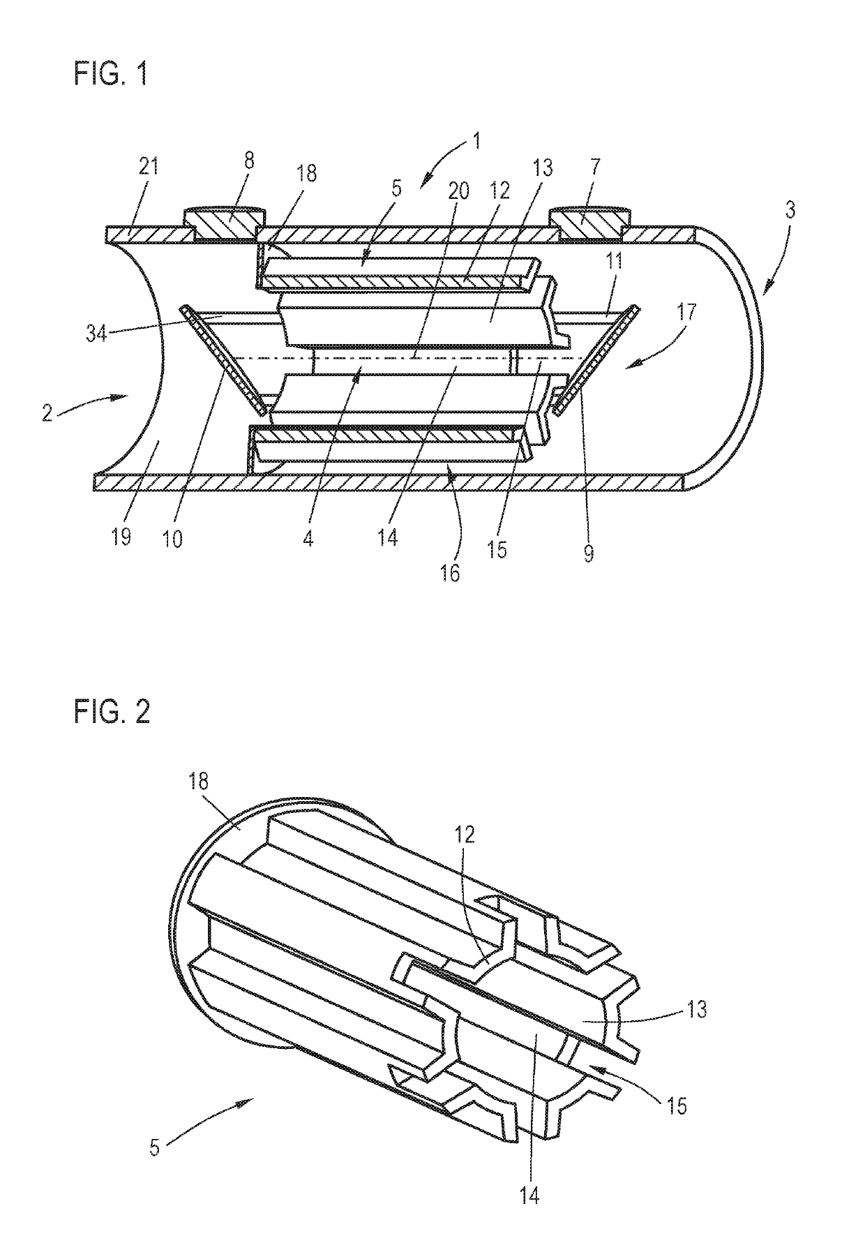
[0044]Referring now to the figures of the drawings in detail and first, particularly to FIG. 1 thereof, there is shown an ultrasonic meter 1 for detecting a flow rate of a fluid. The ultrasonic meter 1 has a fluid inlet 2 and a fluid outlet 3, which can be connected to a fluid network. A flow passage 4 connects the fluid inlet 2 to the fluid outlet 3. Arranged in the flow passage 4 is a measuring tube 5, which extends in a straight line in one flow direction.

[0045]To measure a flow rate, a speed of flow of a medium is determined by sending an ultrasound signal through the measuring tube 5 substantially parallel to the flow direction and evaluating a propagation time and / or a frequency shift of the ultrasound signal. This procedure is known in principle in the prior art and will not be explained in detail. Ultrasonic transducers 7, 8 for providing or receiving the ultrasound signal are arranged on a side wall of a housing 21, which forms at least sections of the flow passage 4. The u...


PUM


Abstract

An ultrasonic meter detects a flow rate of a fluid. The ultrasonic meter has a fluid inlet, a fluid outlet and a flow passage connecting the fluid inlet to the fluid outlet. The flow passage has a measuring tube, which extends in a straight line in a flow direction. An inner wall of a side wall delimiting a flow cross section of the measuring tube has at least one groove, extending in the flow direction, which enlarges the flow cross section. The side wall has an aperture and / or a step exclusively within the groove, between a normal region and a recessed region in the flow direction. A groove depth of the groove is greater in the recessed region than in the normal region.

Description

CROSS-REFERENCE TO RELATED APPLICATION[0001]This application claims the benefit, under 35 U.S.C. § 119, of German patent application DE 10 2016 013 607.3, filed Nov. 15, 2016; the prior application is herewith incorporated by reference in its entirety.BACKGROUND OF THE INVENTIONField of the Invention[0002]The invention relates to an ultrasonic meter for detecting a flow rate of a fluid, and having a fluid inlet, a fluid outlet and a flow passage connecting the fluid inlet to the fluid outlet. The flow passage has a measuring tube which extends in a straight line in a flow direction.[0003]Ultrasonic meters for detecting flow rates of fluids, e.g. of liquids or gases, especially water, should allow as precise as possible detection of the flow rate, even when the flow is highly dynamic. In particular, detection of the flow rate should be robust in relation to internal and external disturbances. Stabilization of the flow in the measurement zone is essential here. In particular, a sudden...

Claims


Application Information

Patent Timeline
Patent Type & Authority Patents(United States)
IPC IPC(8): G01F1/66G01F15/00
CPCG01F15/00G01F1/662G01P5/24G01P5/245
Inventor SONNENBERG, HANS-MICHAEL
Owner DIEHL METERING
Why Eureka
Try Eureka