Implantable occlusion system

a technology of occlusion system and occlusion plate, which is applied in the field of implantable occlusion plate, can solve the problems of inability to achieve industrially, inability to achieve mechanical properties of membranes with significant differences, and inability to manufacture delicate methods

Active Publication Date: 2019-07-16
UROMEMS
View PDF26 Cites 1 Cited by
  • Summary
  • Abstract
  • Description
  • Claims
  • Application Information

AI Technical Summary

Benefits of technology

[0018]An object of the invention is to design an implantable occlusion system which gives the possibility of getting rid of the drawbacks of the existing systems. In particular, this system should allow measurement of the pressure in the sleeve reliably while being biocompatible, sealed and minimizing the bulkiness of the implantable system and the consumption of energy required for regulating this pressure. Preferably said system should also allow control of the pressure in the sleeve.
[0031]This system has the following advantages. On the one hand, the fact that the sensor is laid out in the casing, allows measurement of the pressure without any remote element (outside the casing) and therefore avoids application of complex connections leaving the casing and the seal of which has to be ensured. Further, biocompatibility is ensured by the casing and therefore does not generate any specific constraint in terms of the design of the sensor. Finally, as the sensor is integrated to the pressurization system of the sleeve, the required bulkiness is minimized.

Problems solved by technology

However such a solution cannot be achieved industrially since it poses problems of integration, bulkiness, seal and biocompatibility of the sensor.
However, such a sensor has several drawbacks.
On the one hand, as the metal membrane of the sensor is thin, the manufacturing methods may be delicate.
Indeed, the mechanical stresses due to thermal effects of the weld on the membrane may have an effect on the stiffness of the membrane which may induce significant disparities in the mechanical properties of the membrane.
The method for assembling the different portions of the system (consisting of several tens of elements) is therefore delicate and costly.
Finally, when the system is implanted, the fibrosis surrounding the different elements of the implant may induce a change in stiffness of the membrane and therefore a drift in the measurements over time.
Another problem to be solved is to be able to apply a defined and specific pressure on the anatomic conduit by consuming a minimum of energy.
In the case of a system based on a pressure regulation, this has the effect of quasi-permanently urging the actuator for stabilizing the pressure at a given set value, with the consequence of inducing excessive electric consumption of the system.
This solution has the drawback of not being very accurate on the applied occlusion pressure.
The fluid provided to the occlusion device in contact with the anatomic conduit to be occluded is therefore generally not sufficient for generating the desired pressure.
Moreover, the bulkiness of such a sensor also poses a problem, insofar that the implantable system has to be of dimensions as reduced as possible and that said system further comprises a fluid transfer device, the volume of which has to be consequent and a battery which also represents a large portion of the volume of the implantable system.
The integration of such a sensor into this system may be difficult due to the bulkiness of said sensor.

Method used


Image

  • Implantable occlusion system
  • Implantable occlusion system
  • Implantable occlusion system

Examples


example 1

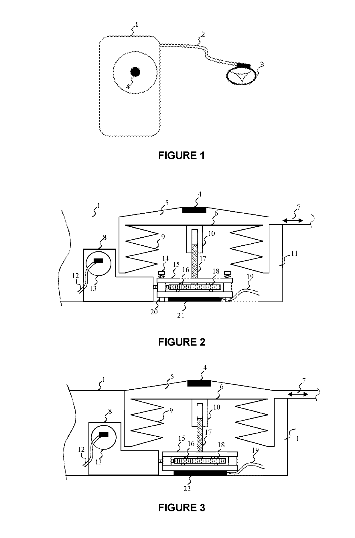
[0190]Measurement of the pressure in the fluidic circuit from a device according to the embodiment described in FIG. 2, comprising a force sensor only measuring compressive forces.

[0191]For i=0 (upper position of the bellows, corresponding to a minimum volume of the reservoir), the processing unit performs the following calculation for measuring the pressure P1 in the fluidic circuit:

[0192]P⁢⁢1=Fsensor-201×10-3

[0193]For a relative zero pressure in the fluidic circuit for example, the force sensor measures the compressive force of the pre-stress (20 N), as well as the force related to the atmospheric pressure difference (900 hPa) exerted on the body of the patient and therefore on the flexible occlusive sleeve and the gas pressure in the casing (1,000 hPa) i.e. a value P1 calculated by the processing unit:

[0194]Fsensor=20⁢⁢N+Seff×(Patm-Pinit)Fsensor=20⁢⁢N+1.10-3×(90000-100000)=10⁢⁢NP⁢⁢1=10-201×10-3=-10⁢⁢kPa

[0195]The relative pressure P2 in the fluidic circuit may be inferred therefro...

example 2

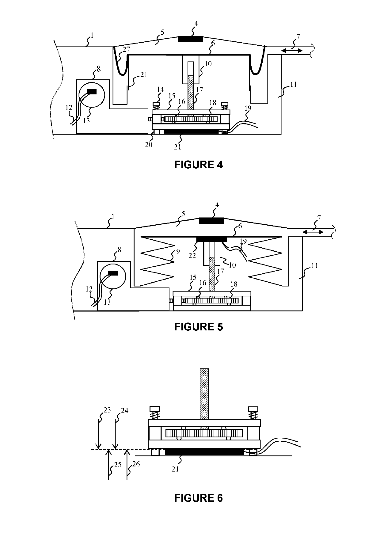
[0213]Measurement of the pressure in the fluidic circuit from a device based on the embodiment described in FIG. 5, comprising a force sensor capable of measuring compressive forces and traction forces.

[0214]For i=0, the processing unit performs the following calculation for measuring the pressure in the fluidic circuit:

[0215]P⁢⁢1=Fsensor1×10-3

[0216]For a zero relative pressure in the fluidic circuit for example, the force sensor only measures a force related to the atmospheric pressure difference (900 hPa) exerted on the body of the patient, and therefore on the flexible occlusive sleeve, and the gas pressure in the casing (1,000 hPa) corresponding to a force of −10N, i.e. a value calculated by the processing unit:

[0217]P⁢⁢1=-101×10-3=-10⁢⁢kPa

[0218]The relative pressure P2 in the fluidic circuit may be inferred therefrom:

P2=P1+(Pinit−Patm)

P2=−10000+(100000−90000)=0 Pa

[0219]For a relative pressure in the fluidic circuit of 5 kPa for example, the only force on the force sensor is the...


PUM


Abstract

An occlusion system implantable in a human or animal body, including a fluidic circuit which includes an inflatable occlusive sleeve, a reservoir with variable volume filled with a fluid. The reservoir includes a fixed portion and a movable portion, an actuator mechanically coupled with the movable portion of the reservoir to linearly displace the movable portion relative to the fixed portion for adjusting the volume of the reservoir. The actuator and the reservoir are laid out in a sealed casing containing a gas. A sensor mechanically bound to the actuator and / or to the movable portion, measures a traction and / or compressive force of the movable portion of the reservoir. Also included is a device for measuring the fluid pressure in the fluidic circuit.

Description

FIELD OF THE INVENTION[0001]The present invention relates to an implantable occlusion system in a human or animal body.BACKGROUND OF THE INVENTION[0002]It is known how to occlude an anatomic conduit by means of an occlusion system implantable into the body of a patient.[0003]The occlusion of the anatomic conduit is ensured by an inflatable sleeve filled with fluid which exerts a more or less strong pressure on the portion to be occluded depending on the volume of the fluid in the inflatable sleeve.[0004]For example, various urinary artificial sphincters are based on this principle for exerting pressure on the urethra. Among known products, mention may be made of the implant referenced as AMS800 marketed by American Medical Systems or else the implant referenced as ZSI375 marketed by Zephyr. The same principle is found in other types of applications such as gastric rings which include an inflatable sleeve placed around the stomach.[0005]The swellable sleeve filled with fluid may be m...

Claims


Application Information

Patent Timeline
Patent Type & Authority Patents(United States)
IPC IPC(8): A61F2/00G16H10/60
CPCA61F2/004A61F2210/0014G16H10/60A61F2250/0003A61F2250/0013A61F2250/001G16H20/40G16H40/63G16H50/20
Inventor LAMRAOUI, HAMID
Owner UROMEMS
Why Eureka
Try Eureka