Rumble strip forming apparatus and method

a technology of forming apparatus and rumble strip, which is applied in the direction of roads, roads, constructions, etc., can solve the problems of increasing the cost of operation for the owner/operator, causing violence, and not being used, so as to reduce the reactive force of the apparatus transporter, smooth, powerful and reliable operation

Active Publication Date: 2019-07-16
WATERBLASTING
View PDF30 Cites 0 Cited by
  • Summary
  • Abstract
  • Description
  • Claims
  • Application Information

AI Technical Summary

Benefits of technology

[0007]The present invention involves the provision of a rumble strip forming apparatus that reduces the amount of reactive force to the apparatus transporter. The rumble strip forming device is mountable on various vehicle chassis for easy transport and use of the device. The rumble strip forming device is powered by the vehicle engine through the use of hydraulics to provide smooth, powerful and reliable operation without undue weight requirements.
[0010]The present invention also provides a profile to the side edges of the formed depression to smooth the transition between the upper and lower surfaces.

Problems solved by technology

These forces cause reactive forces to the machine, often causing violent bouncing of the machine carrying the cutter head and the operator.
Rumble strip forming machines are often single function dedicated machines that, when not in use, are an unnecessary expense to the owner / operator.
This increases the cost of operation to the owner / operator.

Method used


Image

  • Rumble strip forming apparatus and method
  • Rumble strip forming apparatus and method
  • Rumble strip forming apparatus and method

Examples


Embodiment Construction

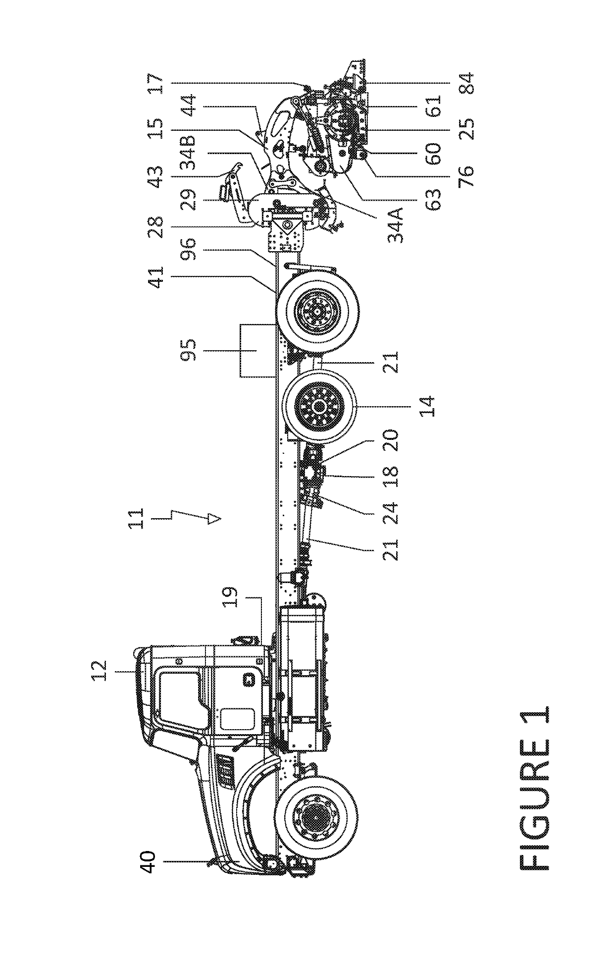
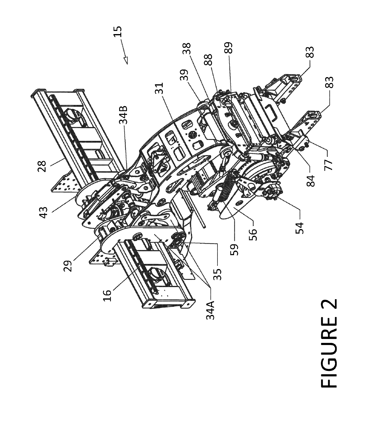
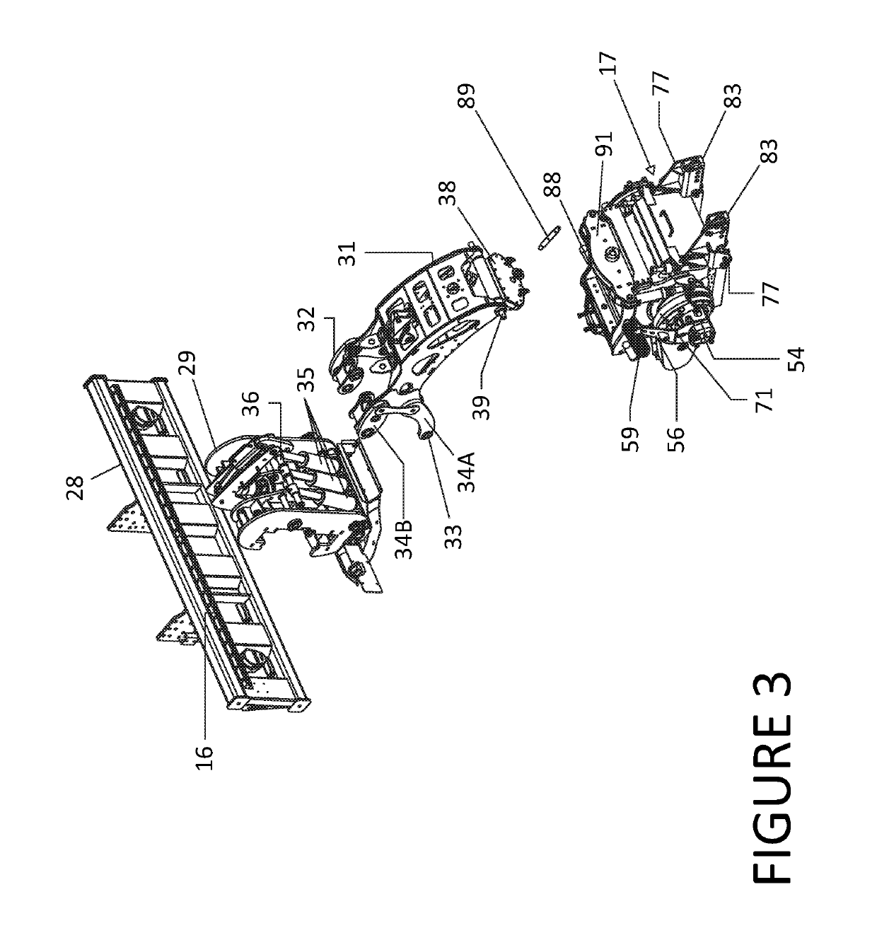
[0028]Now referring to the Figures. The reference numeral 11 designates generally an apparatus for forming rumble strips in a roadway or the like. The formed rumble strip is in the form of a series of elongate grooves cut into the pavement, with the grooves being in spaced apart relationship along the length of the pavement and extending transverse to the direction of vehicle travel. Such rumble strips are well known in the art. They may be on the order of 12 to 18 inches long (transverse to vehicle travel), and 4 to 8 inches wide with a center to center spacing on the order of 6 to 18 inches. They are usually relatively uniformly spaced apart, and are spaced to create noise and vibration in a vehicle having tires passing over the grooves. The apparatus 11 is seen generally in FIG. 1, and, as shown, is comprised of four major components. The first component is in the form of a transport device 12, which is shown as a truck that moves on the pavement via wheels 14. The second compone...


PUM


Abstract

The present device is a rumble strip forming apparatus for reducing the amount of reactive force transferred to the transporter. The rumble strip forming apparatus includes a transport, a lift device, a grinder, and a drive means that connect drive portions of the transport to the grinder to synchronize engagement of a cutting device with the pavement with forward movement of the transport while providing rearward movement of the grinder drum during cutting. The grinder is configured to provide both rotation of a pavement cutter and up and down movement of the pavement cutter while portions of the grinder remain in contact with the pavement.

Description

PRIORITY CLAIM[0001]In accordance with 37 C.F.R. 1.76, a claim of priority is included in an Application Data Sheet filed concurrently herewith. Accordingly, the present invention claims priority to U.S. Provisional Patent Application No. 62 / 475,269, entitled “Rumble Strip Forming Apparatus And Method”, filed Mar. 23, 2017. The contents of the above referenced application are incorporated herein by reference in its entirety.FIELD OF THE INVENTION[0002]An apparatus is provided for forming rumble strips along roadways. The rumble strip apparatus is securable to a vehicle chassis to provide transportation and power to the rumble strip apparatus.BACKGROUND OF THE INVENTION[0003]Numerous machines and methods are available for forming so-called rumble strips along roadways. Rumble strips are provided at the margins of the driving lane so that, when encountered by the wheels of a vehicle, the vehicle is vibrated and sound is generated to inform the driver that the vehicle has wandered from...

Claims


Application Information

Patent Timeline
Patent Type & Authority Patents(United States)
IPC IPC(8): E01C23/00E01C23/09E01F9/529E01C23/088
CPCE01C23/0993E01F9/529E01C23/0946E01C23/088
Inventor CROCKER, JAMES P.
Owner WATERBLASTING
Why Eureka
Try Eureka