Airy beam light sheet and airy beam light sheet microscope

a light sheet and airy beam technology, applied in the field of light sheet imaging, can solve the problems of compromising axial resolution or unnecessarily exposing the sample to irradiation, increasing the size and complexity of the optical setup, and inducing more photo-bleaching and photo-damag

a light sheet and airy beam technology, applied in the field of light sheet imaging, can solve the problems of compromising axial resolution or unnecessarily exposing the sample to irradiation, increasing the size and complexity of the optical setup, and inducing more photo-bleaching and photo-damag

US10353188B2Active Publication Date: 2019-07-16UNIV COURT OF THE UNIV OF ST ANDREWS

Image

  • Airy beam light sheet and airy beam light sheet microscope
  • Airy beam light sheet and airy beam light sheet microscope
  • Airy beam light sheet and airy beam light sheet microscope

Examples


Embodiment Construction

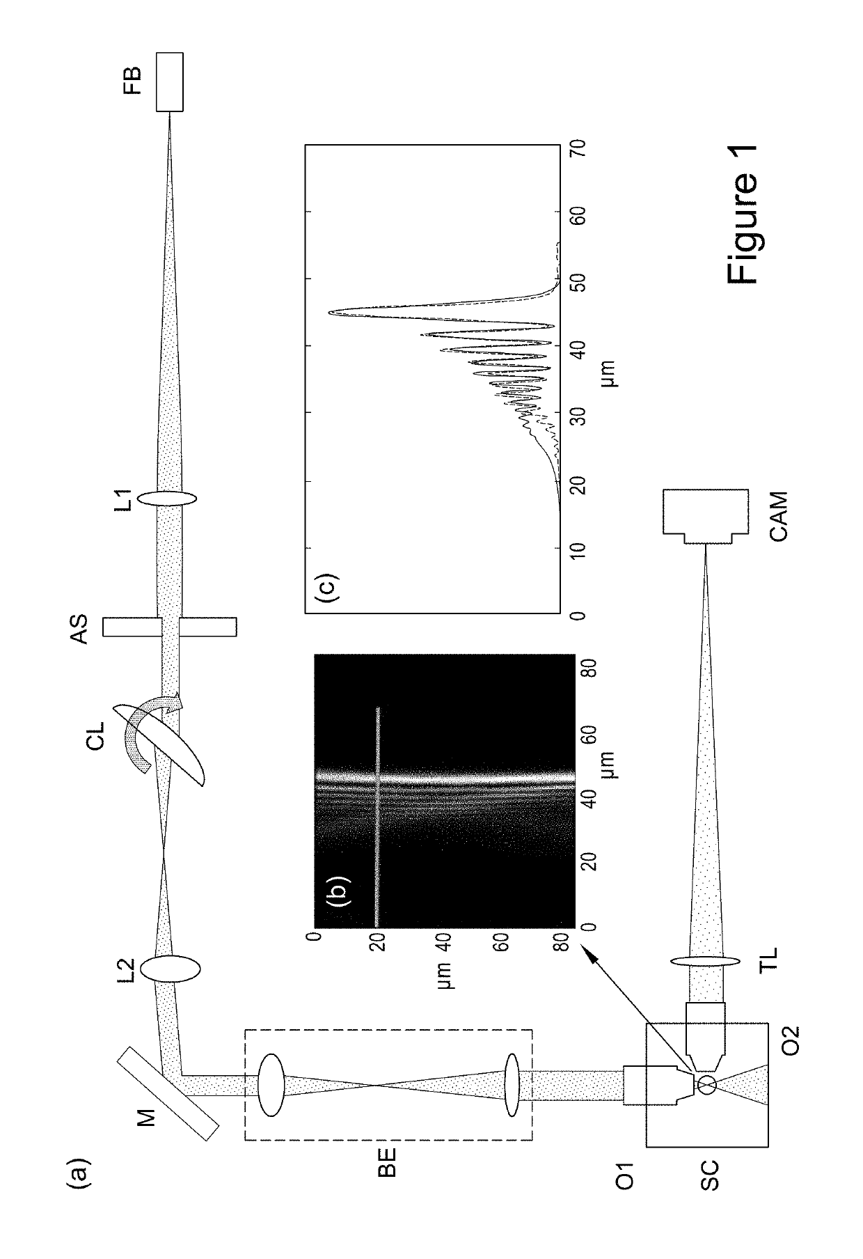
[0035]FIG. 1 shows a single photon Airy beam light sheet microscope. This has a fiber FB for introducing light from a laser. The beam output from the fiber has a Gaussian profile. At an output of the fiber is a first lens L1, which collimates the beam and directs it towards an adjustable slit AS. The adjustable slit AS allows the numerical aperture of the beam to be varied. On the optical path from the adjustable slit AS is a tilted cylindrical lens, which focuses light to a focal point offset from the optical axis. Controlled tilting of the cylindrical lens about the optical axis can induce aberrations that closely approximate the cubic modulation required for Airy light sheet microscopy. Other-order aberration is compensated for using a short-focal-length lens L2, which is positioned after the focal point of the cylindrical lens to re-collimate the beam. The titled cylindrical lens results in lateral displacement of the optical axis. This displacement can be compensated for by adj...


PUM

PropertyMeasurementUnit
focal-lengthaaaaaaaaaa
distanceaaaaaaaaaa
tilt anglesaaaaaaaaaa

Abstract

An optical system for generating an Airy beam light sheet comprising an optical arrangement for generating a Gaussian beam, and an optical element for converting the Gaussian beam into an Airy beam light sheet, wherein a single optical element is provided for converting the Gaussian beam into an Airy beam light sheet.

Description

CROSS-REFERENCE TO RELATED APPLICATION(S)[0001]This application is a national stage application (filed under 35 § U.S.C. 371) of and claims priority to PCT / GB2015 / 052186, filed Jul. 29, 2015 of the same title, which, in turn claims priority to Great Britain Application No. 1413500.8, filed Jul. 30, 2014; the contents of each of which are hereby incorporated by reference.FIELD OF THE INVENTION[0002]The present invention relates to light sheet imaging and in particular a light sheet microscope.BACKGROUND OF THE INVENTION[0003]Light-sheet imaging is rapidly gaining importance for imaging intact biological specimens. Many of the latest innovations rely on the propagation-invariant Bessel or Airy beams to form an extended light sheet to provide high resolution across a large field of view. Shaping light to realize propagation-invariant beams often relies on complex programming of spatial light modulators or specialized, custom made, optical elements.[0004]Light sheet fluorescence microsc...

Claims


Application Information

Patent Timeline
16 Jul 2019
Publication
US10353188B2
IPC
G02B26/00; G02B27/30; G02F1/01; G02B21/06; G02B21/00; G02B26/06; G02B27/09; G02B26/02
CPC
G02B21/06; G02B21/0032; G02B21/0076; G02B26/02; G02B27/30; G02B27/0927; G02B27/0944; G02B27/0966
Inventors
MAZILU, MICHAEL; VETTENBURG, TOM