Method and system for stimulated Raman microscopy beyond the diffraction limit

a raman and microscopy technology, applied in the field of raman and fluorescence microscopy, can solve the problems of limited application of raman process in biological imaging and hyper-resolution, inability to identify intrinsic molecules that are not strongly fluorescent, and inability to identify intrinsic molecules

Inactive Publication Date: 2010-09-23
FREL ROBERT D
View PDF5 Cites 25 Cited by
  • Summary
  • Abstract
  • Description
  • Claims
  • Application Information

AI Technical Summary

Benefits of technology

[0017]According to some embodiments, the temporal width of the coherent pump light pulses may be smaller, for example between 30% and 500% smaller, than the temporal width of the coherent light pulses from the second light sourc

Problems solved by technology

Unfortunately, this technique depends on the presence of efficient fluorescent molecules, where the fluorescence is often provided by a label rather than the intrinsic molecules.
However, this technique is unable to identify intrinsic molecules that are not strongly fluorescent.
Conventional Raman microscopy has several drawbacks that have limited its application in biological imaging and hyper-resolution imaging, with hyper-resolution imaging defined as imaging with a resolution exceeding the diffraction limit.
2) In general, the Raman process is inefficient.
Since high intensity radiation of samples is limited by laser heating, Raman imaging and spectroscopy is a very slow process.
3) The scattering is non-directional, requiring very short working distances or very high numerical aperture lenses and microscope objectives.
4) Spectra of complex organic molecules may overlap, making it difficult to discriminate between different types of molecules.
7) Poor scattering efficiency couple

Method used


Image

  • Method and system for stimulated Raman microscopy beyond the diffraction limit
  • Method and system for stimulated Raman microscopy beyond the diffraction limit
  • Method and system for stimulated Raman microscopy beyond the diffraction limit

Examples


Embodiment Construction

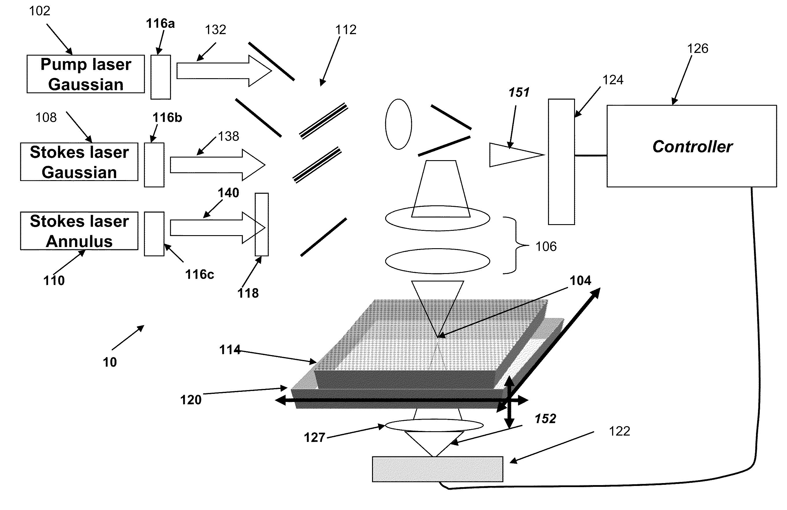
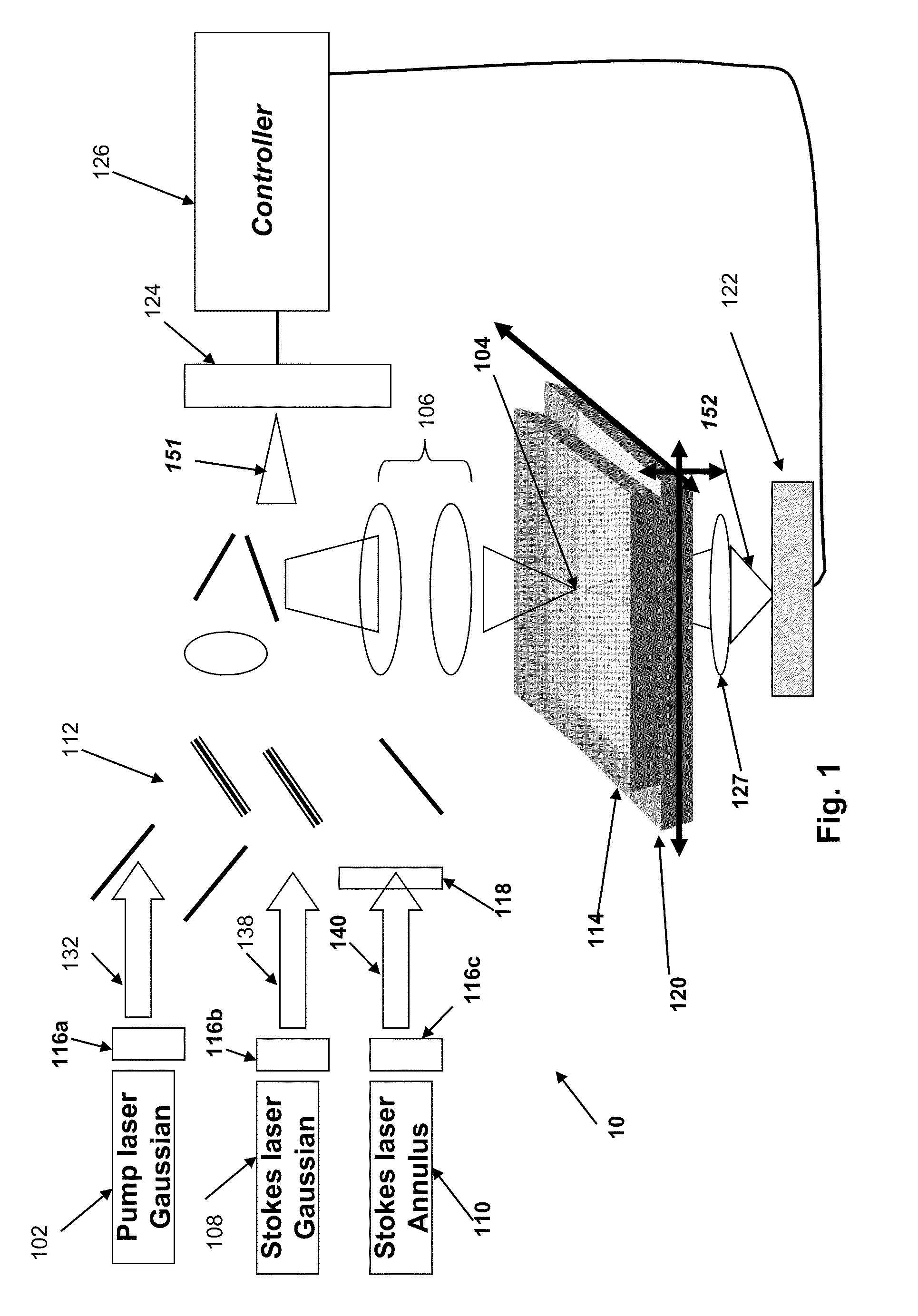
[0029]Referring now to FIG. 1, a microscopy system 10 focuses a pump beam 132 from a pump laser 102 emitting laser pulses with a Gaussian beam profile and picosecond duration in a diffraction limited spot 104 in the focal plane of a high numerical aperture (NA) microscope objective 106. A sample 114 to be investigated is located in or near the focal plane. The laser pulse 132 is used to pump the excited state that will emit stimulated emission. Picosecond laser pulses 138, 140 from two additional lasers 108, 110 that are at Stokes-shifted from the wavelength of the pump laser 102 are also focused at the diffraction limited spot 104. The pulses 138 and 140 from these lasers are referred to as “Stokes” pulses and are used to excite stimulated emission from the excited states of the sample. The energy differences between the pump and the Stokes pulses are within the stimulated emission bandwidth of the sample under study. The picosecond laser pulses 138 and 140 are either emitted so as...


PUM


Abstract

Systems and methods for probing a Raman signature of a sample with a resolution exceeding the diffraction limit are described. These systems, called GASSE (Gain Saturated Stimulated Emission) and iGASSE (interferometric GASSE), are detecting a Raman signal produced in a sample located at the focal spot of a Gaussian pump pulse. Two additional pulsed laser beams (Stokes beams), a central Stokes beam having a Gaussian beam profile and another Stokes beam having an annular beam profile, are also focused to the focal spot. The spatial and temporal phases of the laser pulses are adjusted to produce destructive interference over most of the temporal width of Stokes pulses, which causes emission from the central Stokes beam to narrow well below the diffraction limit. A two-dimensional image of the sample is produced by scanning the combined beams across the sample. The system may find applications in biomedical and semiconductor technology.

Description

FIELD OF INVENTION[0001]This invention relates to the field of Raman and fluorescence microscopy, and more particularly to the field of stimulated Raman and stimulated fluorescence microscopy to image the presence of specific molecular bonds to identify molecules with a resolution beyond the diffraction limit.BACKGROUND TO THE INVENTION[0002]The resolution limit in traditional optical microscopy is limited by the numerical aperture of the microscope (NA) and the wavelength λ of imaging light, generally referred to as Raleigh limit or diffraction limit; and is equal to 0.61(NA)λ. This limit has recently been overcome in the case of fluorescence microscopy with Stimulated Emission Depletion (STED) microscopy by applying the statistical localization techniques of Photo Activation Localization Microscopy (PALM) and STochastic Optical Reconstruction Microscopy (STORM). These techniques are based on the physics of incoherently driven optical fluorescent transitions in dyes or other fluore...

Claims


Application Information

Patent Timeline
IPC IPC(8): G01J3/44G02B21/06
CPCG01J3/44G01N21/6458G02B21/06G01N2021/655G01N21/65
Inventor FRANKEL, ROBERT D.
Owner FREL ROBERT D
Why Eureka
Try Eureka