Tunable gain-clamped semiconductor optical amplifier
a semiconductor optical amplifier and gain clamping technology, applied in semiconductor lasers, laser details, electrical equipment, etc., can solve problems such as drawbacks of gain clamping to a given valu
- Summary
- Abstract
- Description
- Claims
- Application Information
AI Technical Summary
Problems solved by technology
Method used
Image
Examples
second embodiment
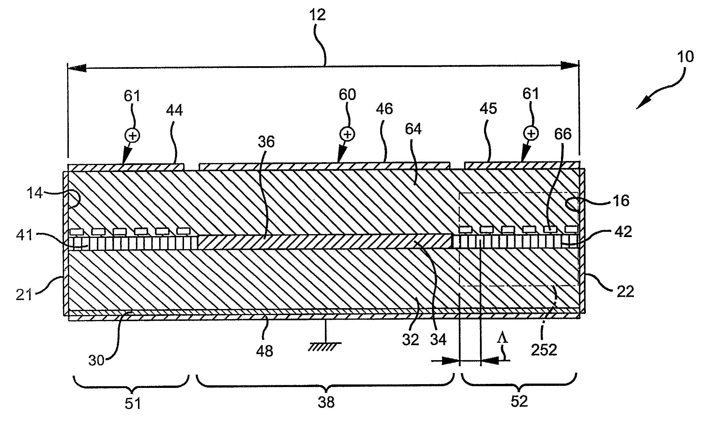
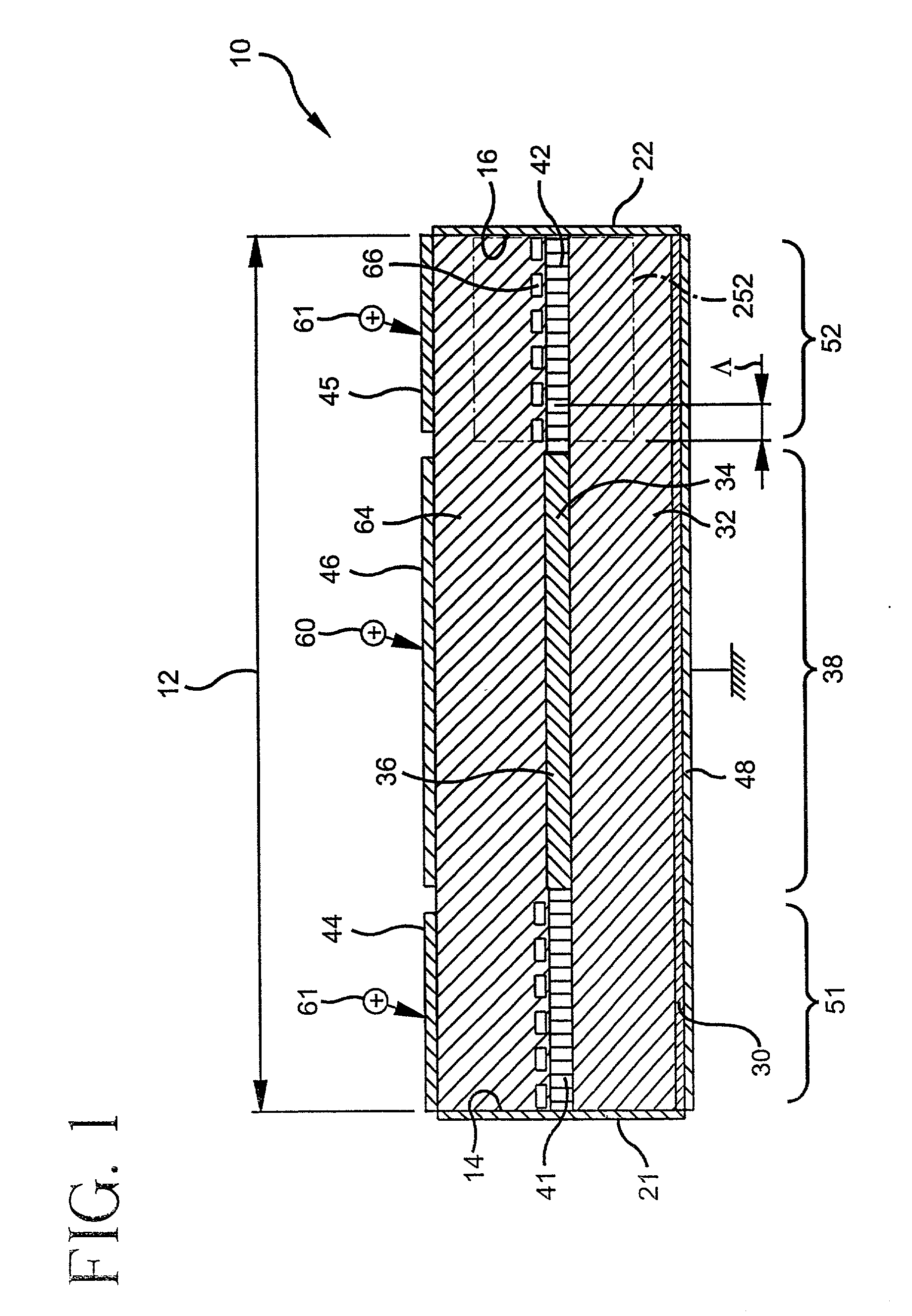
[0071] In accordance with FIG. 5, this relationship is changed to include a dependence on the Bragg wavelength in the following revised equation 1a:
g(.lambda..sub.B, I.sub.amp.sup.th)=.alpha.-(1 / L)ln(r.sup.2)=g.sub.th (1a)
[0072] When the wavelength .lambda. does not equal the Bragg wavelength and the amplifying current injected or biased in the amplifying section 38 becomes higher than the threshold current, I.sub.amp.sup.th, the gain becomes fixed or clamped at g(.lambda., I.sub.amp.sup.th).
[0073] Referring to this power versus wavelength graph (varying ASE) of FIG. 6, relating to equation1a, and according to the slope of the gain spectrum of the amplifying section 38 in the area of the curve where DBR laser operation is desired (outside the 3 dB optical bandwidth), a variation of the Bragg wavelength, by current injection of the tuning current I.sub.Bragg into each of the first and second Bragg reflector sections 51 and 52, will be translated into a variation of the lasing thresho...
first embodiment
[0077] In accordance with FIG. 4, equation 1 is changed to include a dependence on the Bragg reflectivity in the following revised eq. 1b:
g(I.sub.amp.sup.th)=.alpha.-(1 / L)ln(r(I.sub.Bragg).sup.2)=g.sub.th(I.sub.B-ragg) (1b)
[0078] When no current is injected into the Bragg section, a minimal optical feedback into the amplifying section is obtained, limited by the AR coating deposited on the output facets of the devices and by the residual reflectivity of the Bragg section. In that case and according to equation 1b the gain level for which lasing oscillation occurs is high, higher than the maximum available gain into the device. This is illustrated in FIG. 8 by a threshold gain level (g.sub.th(0)) higher than the optical gain of the device. When a current is injected into the Bragg section, the Bragg reflectivity increases with the index modulation contrast. As a result, and according to FIG. 8, the gain threshold condition decreases and makes it possible to get the equality condition...
PUM
 Abstract
Description
Claims
Application Information
 - R&D
- Intellectual Property
- Life Sciences
- Materials
- Tech Scout
- Unparalleled Data Quality
- Higher Quality Content
- 60% Fewer Hallucinations
Browse by: Latest US Patents, China's latest patents, Technical Efficacy Thesaurus, Application Domain, Technology Topic, Popular Technical Reports.
© 2025 PatSnap. All rights reserved.Legal|Privacy policy|Modern Slavery Act Transparency Statement|Sitemap|About US| Contact US: help@patsnap.com


