
Method and system for raman, fluorescence, lithographic, stimulated emission and photochemical imaging beyond the diffraction limit

a raman and emission technology, applied in the field of coherent anti-stokes raman scattering (cars), fluorescence, lithographic, stimulated fluorescence, etc., can solve the problems of limited application of raman process in biological imaging and hyper-resolution, inability to identify intrinsic molecules that are not strongly fluorescent, and inefficient raman process. to achieve the effect of improving the signal-to-noise ratio

Inactive Publication Date: 2012-03-22
FREL ROBERT D
View PDF1 Cites 30 Cited by
  • Summary
  • Abstract
  • Description
  • Claims
  • Application Information

AI Technical Summary

Benefits of technology

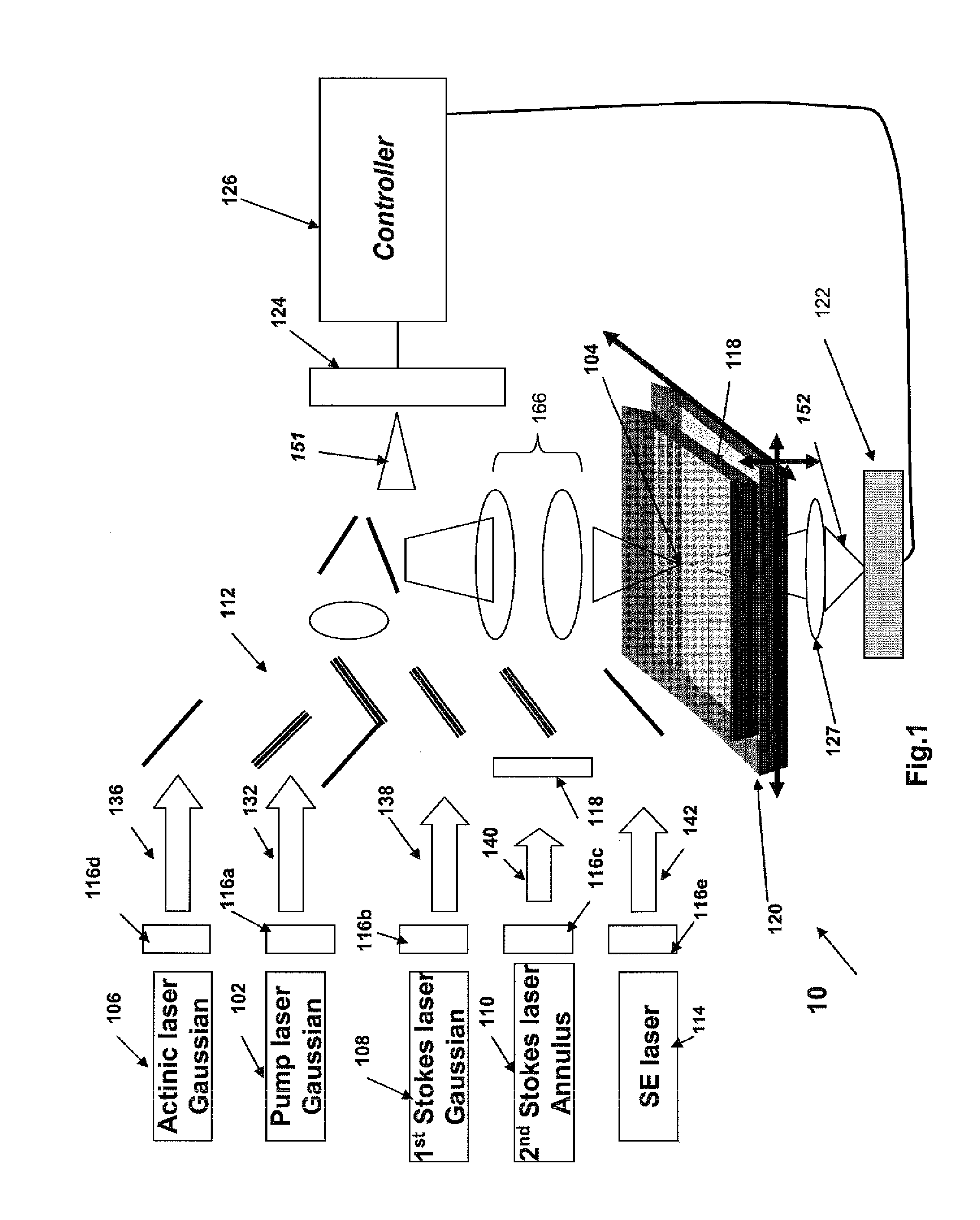
[0015]The systems and methods described herein make use of four and optionally five laser beams. Two laser beams, referred to as pump beam and Stokes beam, are used for vibrational level excitation in a target molecule, creating a transient change in the absorption profile of the target molecule by populating a vibrational excited state. Another beam, referred to as interfering or annulus beam, is used to narrow the vibrational excited state spatial distribution enabling imaging resolution beyond the diffraction limit of a microscope by interfering with the Stokes beam. The fourth laser beam, referred to as actinic beam, provides the population of the electronic excited state that either creates fluorescence (enhancing the molecular Raman signal, either with or without the use of the interfering beam), initiates a hyper-resolution photochemical event pattern or produces hyper-resolution CARS imaging in a scanning microscope. The actinic beam may also provide the contrast in absorption microscopy. In some embodiments, as described below, a fifth laser beam referred to as the Stimulated Emission (SE) laser beam may be added to the system to produce stimulated emission from the excited state of the fluorescent molecule.
[0017]According to another feature of the present invention, the added energy of two photons from the pump laser beam may be selected so that their sum is less than the resonant excitation energy of the target molecule. These photons may have a wavelength between 380 nm and 1000 nm depending on the energy of the electronic transition. This minimizes parasitic two-photon absorption effects. In an alternative choice of the two-photon summed energy of beam, the energy of one beam is greater than the first excited state manifold of the target molecule, but less than the lowest excited state of the second excited state manifold of the molecule. These photons may have a wavelength between 250 nm and 500 nm depending on the energy of the electronic transition. However, the added energy of the two beams should also be less than the energy of the second excited state.

Problems solved by technology

Unfortunately, this technique depends on the presence of efficient fluorescent molecules, where the fluorescence is often provided by a label rather than the intrinsic molecules.
However, this technique is unable to identify intrinsic molecules that are not strongly fluorescent.
Conventional Raman microscopy has several drawbacks that have limited its application in biological imaging and hyper-resolution imaging, with hyper-resolution imaging defined as imaging with a resolution exceeding the diffraction limit.
2) In general, the Raman process is inefficient.
Since high intensity radiation of samples is limited by laser heating, Raman imaging and spectroscopy is a very slow process.
3) The scattering is non-directional, requiring very short working distances or very high numerical aperture lenses and microscope objectives.
4) Spectra of complex organic molecules may overlap, making it difficult to discriminate between different types of molecules.
7) Poor scattering efficiency coupled with poor discrimination of signal and background makes detection of low concentrations of molecules impossible.
These fast excited state decays make it impossible to use STED imaging techniques to achieve hyper-resolution imaging.
Alternatively, using resonant Raman spectroscopy can increase the Raman scattering cross section to 10−4 efficiency, albeit at the expense of significant enhanced fluorescent emission, and in tissues this is limited by the very strong background absorption in the ultraviolet (UV).
However, most molecules have resonant absorption in the UV region which limits the use in plastic containers or the ability to see below the surface of biological tissues.
Furthermore UV light often causes significant damage to biological and plastic materials, limiting its use to thin or surface samples.
Disadvantageously, the traditional CARS process produces a non-resonant incoherent background which can mask the measurement signal.
CARS also lacks adequate sensitivity, has a resolution limited to at most 300-400 nm, and cannot distinguish overlapping Raman bands.
However the femtosecond to picosecond lifetime of the excited states of these molecules have limited the application of STED techniques for use with these techniques for hyper-resolution imaging.
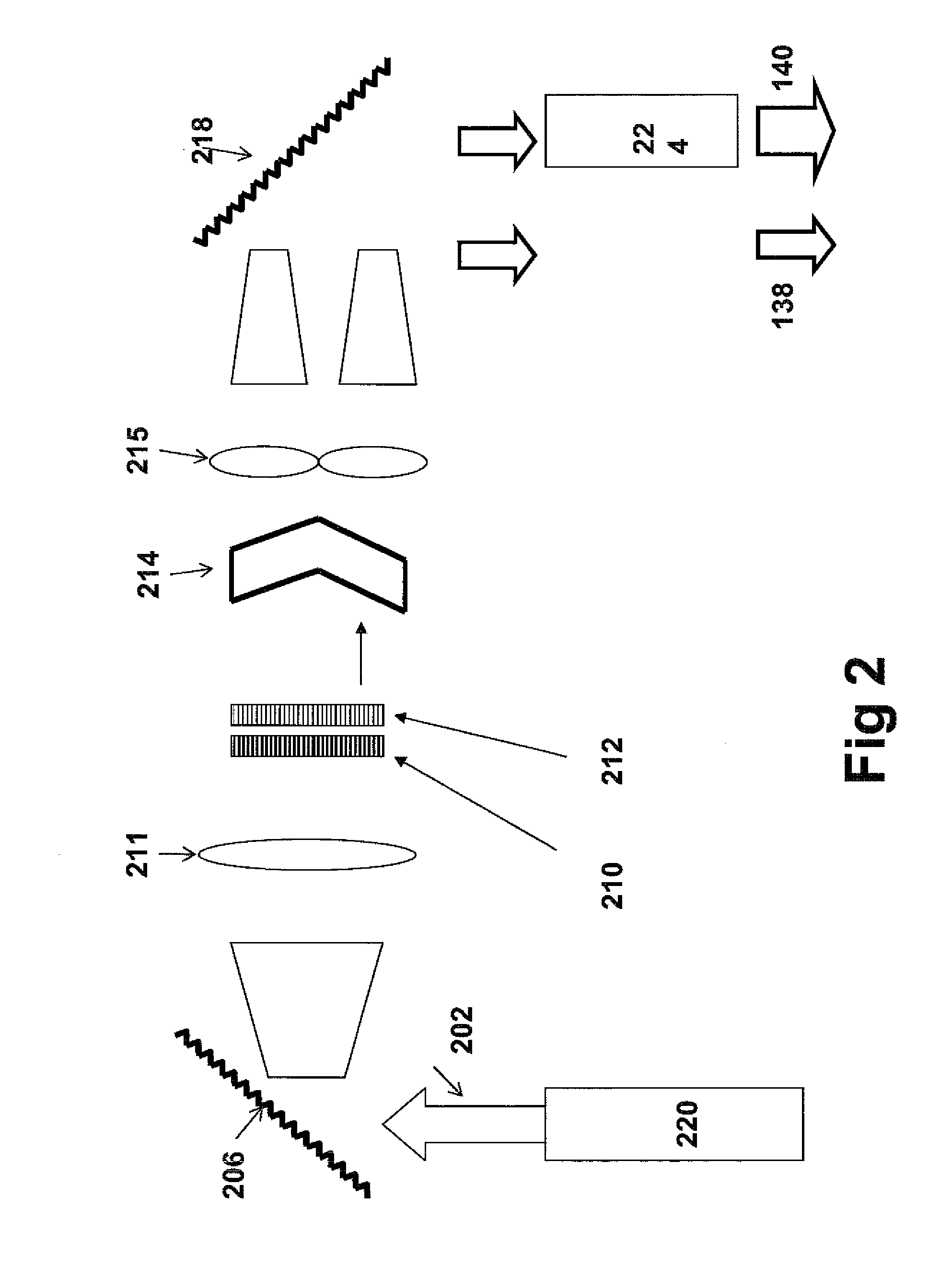
Alternatively, the annular pulse is designed to be 180° out of phase of the central pulse and thus destructive interference reduces the gain over most of the temporal width of Stokes pulses which causes emission from the central Stokes beam to narrow well below the diffraction limit.
It can image deeply below the surface which is not possible with resonance Raman techniques operating in the UV.
However, there are hyper-resolutions imaging situations which cannot be solved with GASSE imaging.
In addition GASSE does not provide hyper resolution in absorption microscopy, or on stimulated CARS imaging or resonant CARS imaging.

Method used


Image

  • Method and system for raman, fluorescence, lithographic, stimulated emission and photochemical imaging beyond the diffraction limit
  • Method and system for raman, fluorescence, lithographic, stimulated emission and photochemical imaging beyond the diffraction limit
  • Method and system for raman, fluorescence, lithographic, stimulated emission and photochemical imaging beyond the diffraction limit

Examples


Embodiment Construction

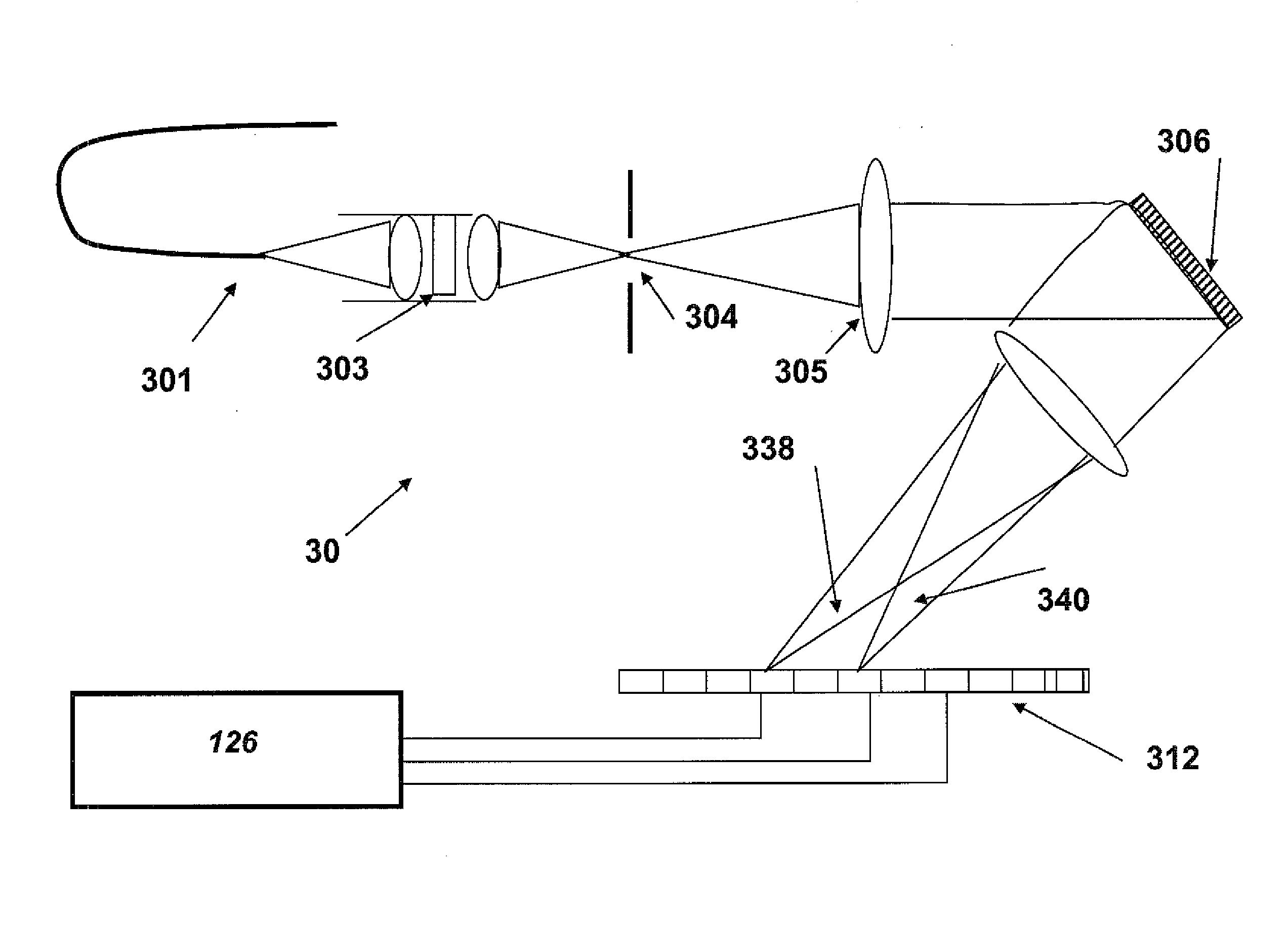
[0035]Throughout all the figures, same or corresponding elements may generally be indicated by same reference numerals. These depicted embodiments are to be understood as illustrative of the invention and not as limiting in any way. It should also be understood that the figures are not necessarily to scale and that the embodiments are sometimes illustrated by graphic symbols, phantom lines, diagrammatic representations and fragmentary views. In certain instances, details which are not necessary for an understanding of the present invention or which render other details difficult to perceive may have been omitted.

[0036]Referring now to FIG. 1, a laser system10 includes four lasers 102, 106, 108 and 110, as well as an additional (optional) laser 114. The laser 102 is referred to as pump laser emitting laser pulses of picosecond duration with a Gaussian beam profile in form of a pump beam 132. The pump beam 132 is focused in a diffraction limited spot 104 in the focal plane of a high n...


PUM

PropertyMeasurementUnit
wavelengthaaaaaaaaaa

Abstract

Systems and methods for hyper-resolution beyond the diffraction limit of optical microscopes for applications in spectroscopy, absorption and lithographic photochemical patterning are described. These systems are based on interference of a pump pulse and a Stokes laser pulse which interfere to localize the population of an excited vibrational state in an area that is smaller than the scanning resolution of the microscope. Another (interfering) Stokes pulse has an annular shape at focus and destructively interferes with the the Stokes laser pulse. This destructive interference causes narrowing of the population distribution of the vibrational excited state well below the diffraction limit, which in turn localizes the population of the central electronic excited state by a separate actinic laser pulse having a lower energy than the ground state excitation energy of the molecule.A stepped photolithography system uses two photomasks to produce photoresist images capable of printing features smaller than 10 nm.

Description

CROSS-REFERENCE TO RELATED APPLICATIONS[0001]This application claims the benefit of prior filed U.S. provisional Application No. 61 / 384,558, filed Sep. 20, 2010, the entire content of which is incorporated herein by reference.FIELD OF INVENTION[0002]This invention relates to the field of Coherent Anti-Stokes Raman Scattering (CARS), fluorescence, absorption, stimulated fluorescence, stimulated Raman and lithographic photochemical patterning microscopy, and more particularly to the field of non-linear two to four-wave coherent and incoherently mixed optical imaging in the presence of specific molecular bonds that are used to identify and image molecules, or to induce patterned photochemistry in the molecules with a resolution beyond the diffraction limit of the microscopic imaging system being used.BACKGROUND TO THE INVENTION[0003]The following discussion of related art is provided to assist the reader in understanding the advantages of the invention, and is not to be construed as an...

Claims


Application Information

Patent Timeline
Patent Type & Authority Applications(United States)
IPC IPC(8): G01J3/44G21K5/00G01J3/30G01N21/64
CPCG01J3/10G01J3/44G01N21/6458G03F7/2051G01N2021/653G01N2021/655G01N21/65G03F7/2053
Inventor FRANKEL, ROBERT D.
Owner FREL ROBERT D
Learn More