Hand tool for welding-torch maintenance

a technology for welding nozzles and tools, applied in multi-purpose tools, manufacturing tools, pliers, etc., can solve the problems of poor working efficiency and difference between removing sputters from nozzles, and achieve the effect of sufficient working efficiency

Active Publication Date: 2019-08-13
SEVENTY EIGHT CO LTD
View PDF23 Cites 3 Cited by
  • Summary
  • Abstract
  • Description
  • Claims
  • Application Information

AI Technical Summary

Benefits of technology

[0008]Accordingly, it is an object of the present invention to provide a hand tool for welding-torch maintenance which can remove sputter adhering to a nozzle with sufficient working efficiency.
[0010]According to the present invention, the sputter adhering to the inner circumferential surface, the outer circumferential surface, and also the end face of the nozzle can be removed by inserting the 1st pinchings into the nozzle, putting the end of the nozzle between the 2nd pinchings and the 1st pinchings, and by moving the hand tool so that the inner-and-outer circumferential surfaces and the end face of the nozzle may be scratched. Therefore, it is possible to remove the sputter adhering to the inner circumferential surface, the outer circumferential surface, and also the end face of the nozzle by such work for moving the hand tool after putting the end of the nozzle between the 2nd pinchings and the 1st pinchings, and the removal of the sputter adhering to the nozzle can be done with sufficient working efficiency.

Problems solved by technology

However, in the usage of the conventional hand tool mentioned above, there is a difference between when removing the sputter adhering to the inner-and-outer circumferential surfaces of the nozzle and when removing the sputter adhering to the end face of the nozzle.
Consequently, each of the work for removing the sputter adhering to the inner-and-outer circumferential surfaces of the nozzle and the work for removing the sputter adhering to the end face of the nozzle falls into a different work processes, and the working efficiency in removing the sputter adhering to the nozzle is no good.

Method used


Image

  • Hand tool for welding-torch maintenance
  • Hand tool for welding-torch maintenance
  • Hand tool for welding-torch maintenance

Examples


Embodiment Construction

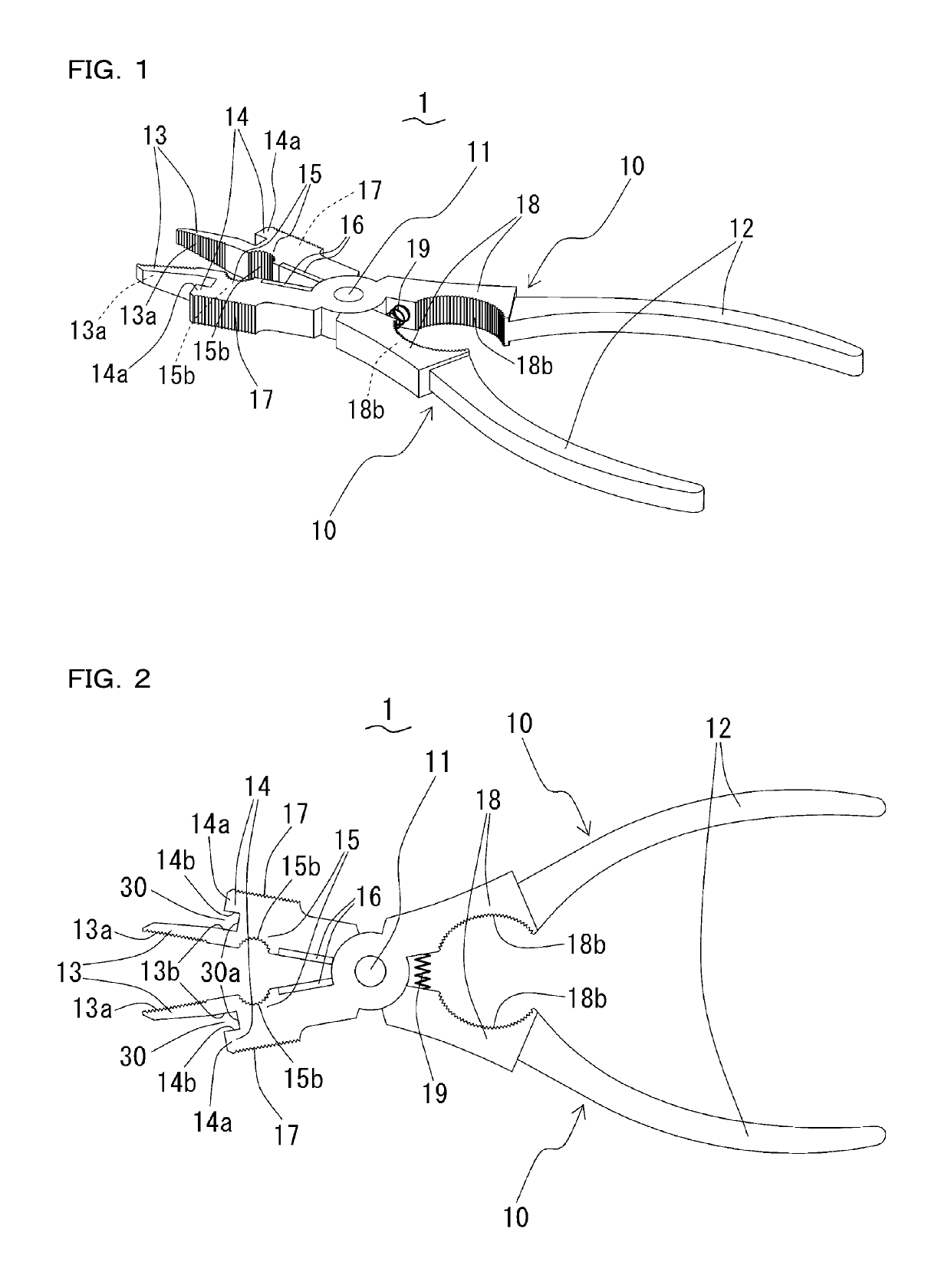
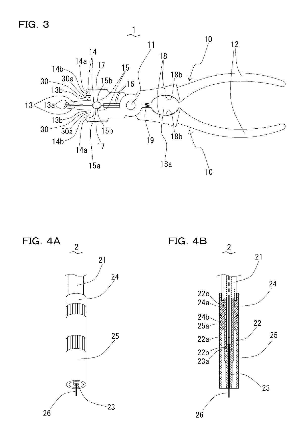
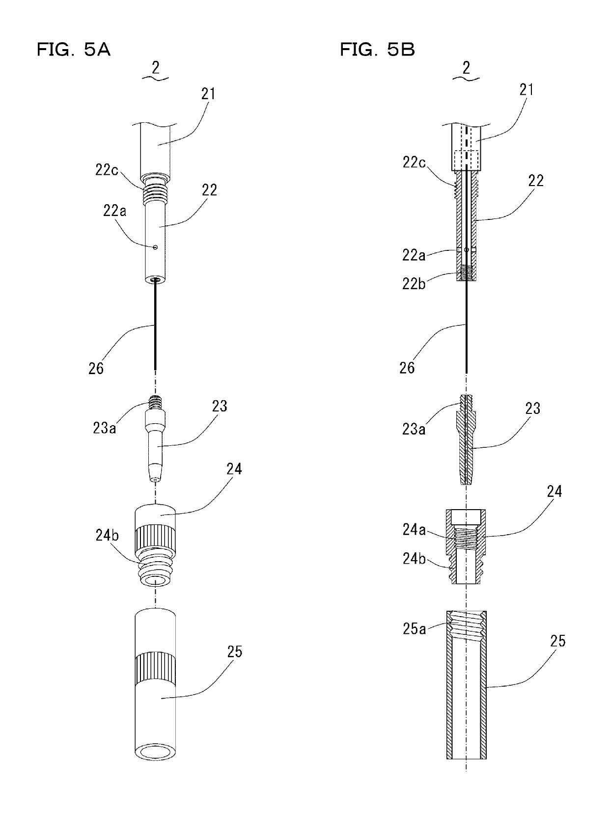
[0026]Hereafter, a hand tool for welding-torch maintenance according to an embodiment of the present invention is explained with reference to drawings. FIG. 1, FIG. 2, and FIG. 3 show a hand tool 1 for welding-torch maintenance, and FIG. 4A, FIG. 4B, FIG. 5A, and FIG. 5B show a welding-torch 2. The hand tool 1 is a hand tool used in order to maintain the welding-torch 2, and is a hand tool used for disassembly and assembly of the welding-torch 2 and removal of sputter adhering to the welding-torch 2, etc.

[0027]Here, the welding-torch 2 is explained with reference to FIG. 4 and FIG. 5. The welding-torch 2 is attached to automatic-welding equipment for arc welding, and comprises: a torch body 21 held on a robot arm of the automatic-welding equipment (not shown); a chip body 22 attached to the torch body 21; a chip 23 and an insulator (insulating pipe) 24 which are attached to the chip body 22 detachably and attachably; and a nozzle 25 attached to the insulator 24 detachably and attach...


PUM

PropertyMeasurementUnit
timeaaaaaaaaaa
shapeaaaaaaaaaa
poweraaaaaaaaaa

Abstract

A hand tool for welding-torch maintenance, which can remove sputter adhering to a nozzle with sufficient working efficiency. The hand tool has a pair of metal stays turnably supported by a pivoting axis. The metal stays comprises grips handled by a user, 1st pinchings used for pulling a welding-wire, and 2nd pinchings used for removing sputter adhering to the nozzle. The 1st pinchings are configured so as to be inserted into the nozzle when the metal stays are closed. The 2nd pinchings have projections which are extended outside from the backs of the 1st pinchings and thrown out towards heads of the 1st pinchings. The sputter adhering to the inner-and-outer circumferential surfaces and end face of the nozzle are removed by inserting the 1st pinchings into the nozzle, inserting the end of the nozzle between the 2nd pinchings and the 1st pinchings, and moving the tool to scratch the sputter off the inner-and-outer circumferential surfaces and the end face of the nozzle.

Description

FIELD OF THE INVENTION[0001]The present invention relates to a hand tool used to maintain a welding-torch with which welding equipment is equipped, and particularly relates to a hand tool for welding-torch maintenance used for disassembly and assembly of a welding-torch and removal of sputter adhering to the welding-torch, etc.BACKGROUND OF THE INVENTION[0002]In a welding-torch of an automatic-welding equipment for arc welding, the welding torch body is held on a robot arm, and parts, such as a nozzle for sending out shielding gas and a chip for sending out welding-wire, are attached to the torch body in a manner of enabling attachment and detachment. It is necessary to detach parts, such as a nozzle and a chip, from the torch body for check. Moreover, when the arc welding is performed, sputter (particulates dispersed at a time of welding) will adhere to the nozzle. The sputter adhering to the nozzle has a bad influence on sending out of the shielding gas. For this reason, it is nec...

Claims


Application Information

Patent Timeline
Patent Type & Authority Patents(United States)
IPC IPC(8): B23K9/32B25B7/08B25B7/02B25F1/00B25B7/22
CPCB23K9/328B25B7/02B25F1/003B25B7/22B25B7/08
Inventor MIZUTANI, TETSUYA
Owner SEVENTY EIGHT CO LTD
Why Eureka
Try Eureka