
System and method for empirical ensemble-based virtual sensing of gas emission

Inactive Publication Date: 2010-12-23
INSTITUTT FOR ENERGITEKNIKK
View PDF1 Cites 5 Cited by
  • Summary
  • Abstract
  • Description
  • Claims
  • Application Information

AI Technical Summary

Benefits of technology

[0041]The present invention solves the problems of accuracy, robustness, stability and simplicity of a virtual sensor suitable for gas sensing by a combination of empirical modelling with ensemble modelling.
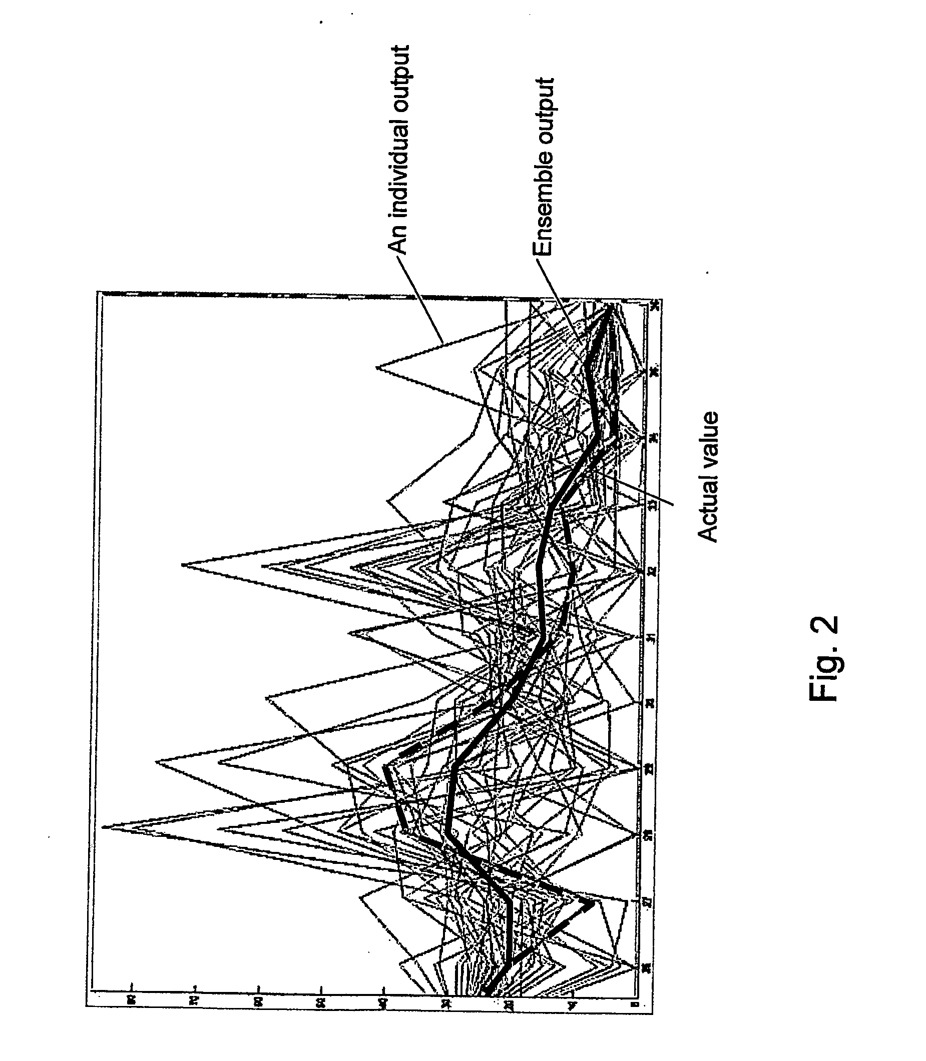
[0051]It is shown that the average calculation, in addition to be easy to implement also makes it possible to achieve a required accuracy that may not be possible with single-node virtual sensors.
[0052]In an embodiment of the present invention all the empirical models or inner nodes may have identical structure. This setup has the advantage that the required number of inner nodes can simply be instantiated in the virtual sensor system based on a template node. Further, the nodes may all be arranged for receiving the same set of signal input values from the sensors of the combustion process. Signals from the sensors are distributed to all the nodes, and the extra work of handling special cases is avoided.
[0053]In an embodiment the accuracy of the virtual sensor system according to the invention may be increased by instantiating a larger number of empirical models. Thus, it is not necessary to increase the complexity of the system to increase the accuracy. This way of achieving a better result simply by increasing the size of the ensemble is different from other methods that e.g. emphasise the selection of the ensemble.

Problems solved by technology

However it is problematic to develop good sensors, due to the harsh operating environment with e.g. high temperatures and soot.
The sensitivity that is needed is high, typically the levels of NO are around 100-2000 ppm and NO2 20-200 ppm, and there are various sources of error such as cooling from the gas flow.
These could be air, water, oil, or material samples that are analysed to control environmental emission, product quality, or process condition.2. The available physical sensor is too slow, in particular for use in automatic control.3. The physical sensor is too far downstream, e.g the end product is continuously monitored to detect production deviations, but where this information comes too late to perform corrective action.4. The physical sensor is too expensive.5. There are no means of installing a physical sensor, e.g. no physical space.6. The sensor environment is too hostile.7. The physical sensor is inaccurate.
Available physical sensors might be subject to either intrinsic inaccuracies or to degradation.
Scaling in a Venturi flow-meter is a typical example.8. The physical sensor is expensive to maintain.
The main weakness of the analytical approach is that it requires accurate quantitative mathematical models in order to be effective.
For large-scale systems, such information may not be available or it may be too costly and time consuming to compile.
Accurate extrapolation, i.e. providing estimations for data that resides outside of the training data, is either not possible or not reliable for most empirical models.
When plant conditions or operations change significantly, the model is forced to extrapolate outside the learned space, and the results will be of low reliability.
Extrapolation, even if using a linear model, is not recommended for empirical models since the existence of pure linear relationships between measured process variables is not expected.
Furthermore, the linear approximations to the process are less valid during extrapolation because the density of training data in these extreme regions is either very low or non-existent.
Accordingly, the computational requirements lead to an upper limit on model size which is typically more limiting than that for other empirical model types.
When networks disagree: ensemble methods for hybrid neural networks, National Science Fundation, USA) Obviously, the combination of identical models would produce no performance gain.

Method used


Image

  • System and method for empirical ensemble-based virtual sensing of gas emission
  • System and method for empirical ensemble-based virtual sensing of gas emission
  • System and method for empirical ensemble-based virtual sensing of gas emission

Examples


Embodiment Construction

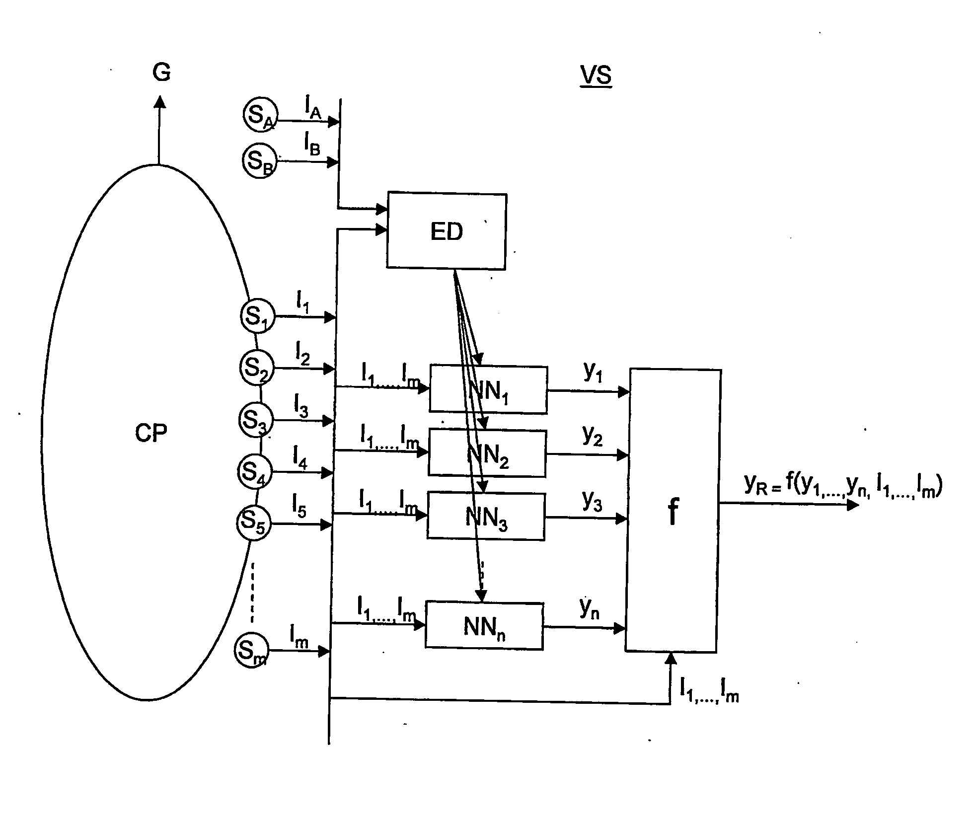
[0064]FIG. 1 is a block diagram of an embodiment of a virtual sensor system used to measure the amount of a gas (G) resulting from a combustion process (CP) according to the present invention.

[0065]In an embodiment of the present invention the ensemble based virtual sensor system (VS) for the estimation of an amount of a gas (G) resulting from a combustion process (CP) comprises two or more empirical models (NN1, NN2, . . . , NNn) where each of the empirical models (NN1, NN2, . . . , NNn) are arranged for estimating the amount of gas (G), and a combination function (f) is arranged for combining the results from the empirical models (NN1, NN2, . . . , NNn) to provide an estimation of the amount of gas (G) that is more accurate than the signal output value (y1, y2, . . . , ym) from each of the individual empirical models (NN1, NN2, . . . , NNn) The amount of gas (G) can be given as the concentration or mass emission as understood by a person with ordinary skills in the art. Examples o...


PUM


Abstract

An empirical ensemble based virtual sensor system (VS) for the estimation of an amount of a gas (G) resulting from a combustion process (CP) comprising two or more empirical models (NN1, NN2, . . . , NNn). The amount of gas (G) is estimated in each of the empirical models (NN1, NN2, . . . , NNn), and a combination function (f) combines the results from the empirical models (NN1, NN2, . . . , NNn) to provide a combined estimate for the amount of gas (G) that is more accurate than the estimated amount of gas from each of the individual empirical models (y1, y2, . . . , ym). The total performance of the virtual sensor system (VS) may be increased by increasing the number of empirical models (y1, y2, . . . , ym).

Description

TECHNICAL FIELD[0001]The present invention relates to a method and system for empirical ensemble-based virtual sensing and more particularly to a method and system for virtual gas sensors for measuring the emission, such as NOx, CO2 etc. from combustion processes.BACKGROUND[0002]NOx is a generic term for mono-nitrogen oxides (NO and NO2) that are produced during combustion. NOx can be formed through high temperature oxidation of the diatomic nitrogen found in combustion air. In addition combustion of nitrogen-bearing fuels such as certain coals and oil, results in the conversion of fuel bound nitrogen to NOx.[0003]Atmospheric NOx eventually forms nitric acid, which contributes to acid rain. The Kyoto Protocol, ratified by 54 nations in 1997, classifies NO2 as a greenhouse gas, and calls for worldwide reductions in its emission, as does The Convention on Long-range Transboundary Air Pollution's so called Gothenburg Protocol.[0004]As a result NOx emissions are regulated in a number of...

Claims


Application Information

Patent Timeline
IPC IPC(8): G06N3/08G06F15/18
CPCF01N9/005Y02T10/47G06N3/0454Y02T10/40G06N3/045
Inventor ROVERSO, DAVIDE
Owner INSTITUTT FOR ENERGITEKNIKK
Learn More