Method to Determine a Relative Position of Devices in a Network and Network of Devices for Carrying Out the Method

a technology of relative position and network, applied in the field of method to determine the relative position of devices in a network and the network of devices for carrying out the method, can solve the problems of time-consuming and difficult to activate the device, and achieve the effect of less work

Inactive Publication Date: 2008-10-16
KONINKLIJKE PHILIPS ELECTRONICS NV
View PDF14 Cites 6 Cited by
  • Summary
  • Abstract
  • Description
  • Claims
  • Application Information

AI Technical Summary

Benefits of technology

[0004]It is an object of the invention to provide a method, that is able to provide information on the actual physical position of several devices in a network, with less amount of work.

Problems solved by technology

This is very time consuming, and needs at least one person, and possibly more in case the devices may not be checked from the position of the operator, such as lighting systems in large building etc.
Sometimes it is also difficult to activate the device, such as a street lamp on a high pole.

Method used


Image

  • Method to Determine a Relative Position of Devices in a Network and Network of Devices for Carrying Out the Method
  • Method to Determine a Relative Position of Devices in a Network and Network of Devices for Carrying Out the Method
  • Method to Determine a Relative Position of Devices in a Network and Network of Devices for Carrying Out the Method

Examples


Embodiment Construction

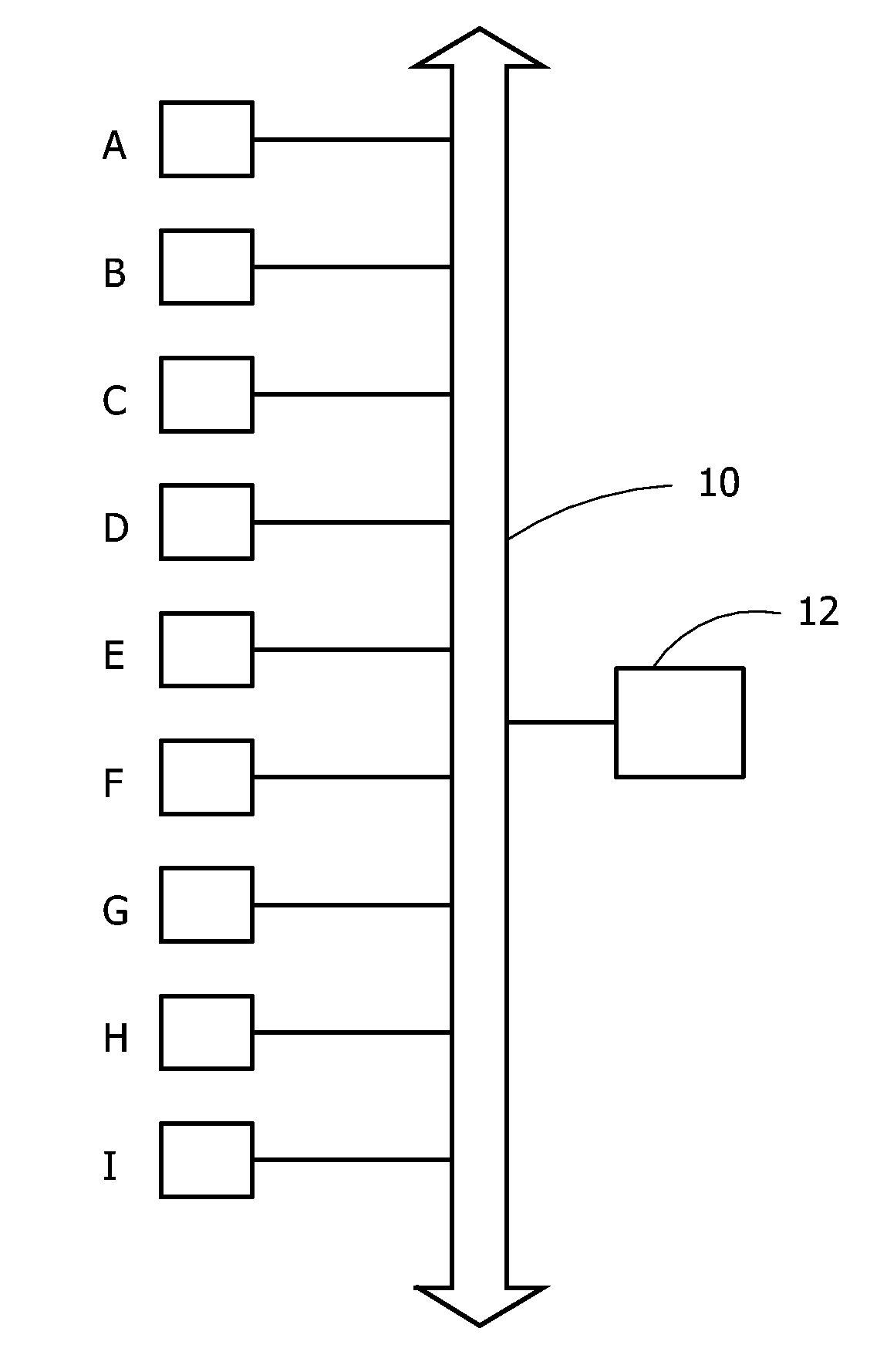
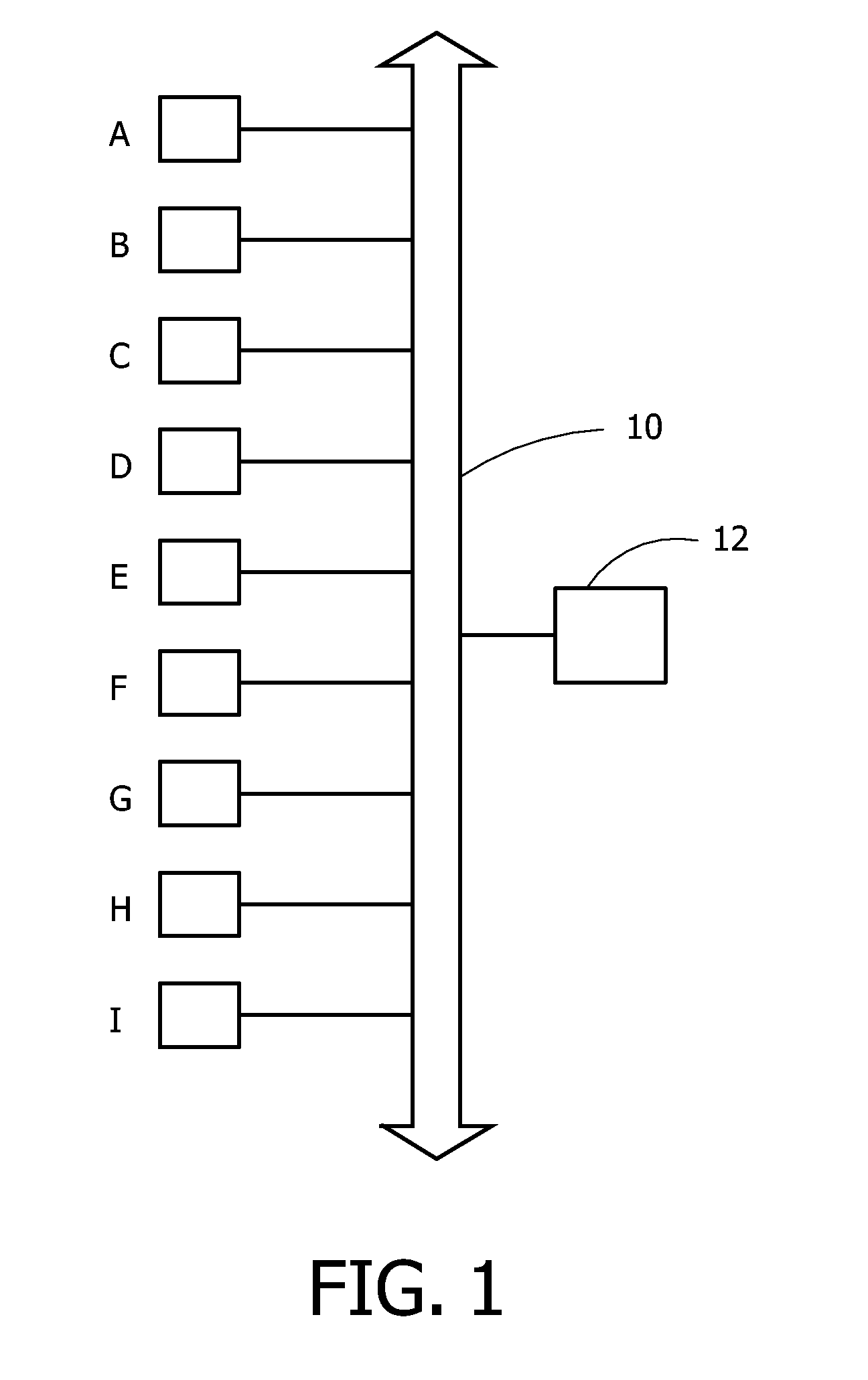
[0042]FIG. 1 shows diagrammatically a network for the method according to the invention. Herein, 10 is a diagrammatic power cable, 12 is a control unit, while A through I are nine devices which are connected via the power cable 10.

[0043]Such a network could e.g. be a lighting network, a video camera circuit, an alarm network and so on. The arrow heads at the ends of the power cable 10 indicate that in each direction more, or less, devices may be connected. Before carrying out the method, the devices have a unique ID, but it is not yet known where those devices are located.

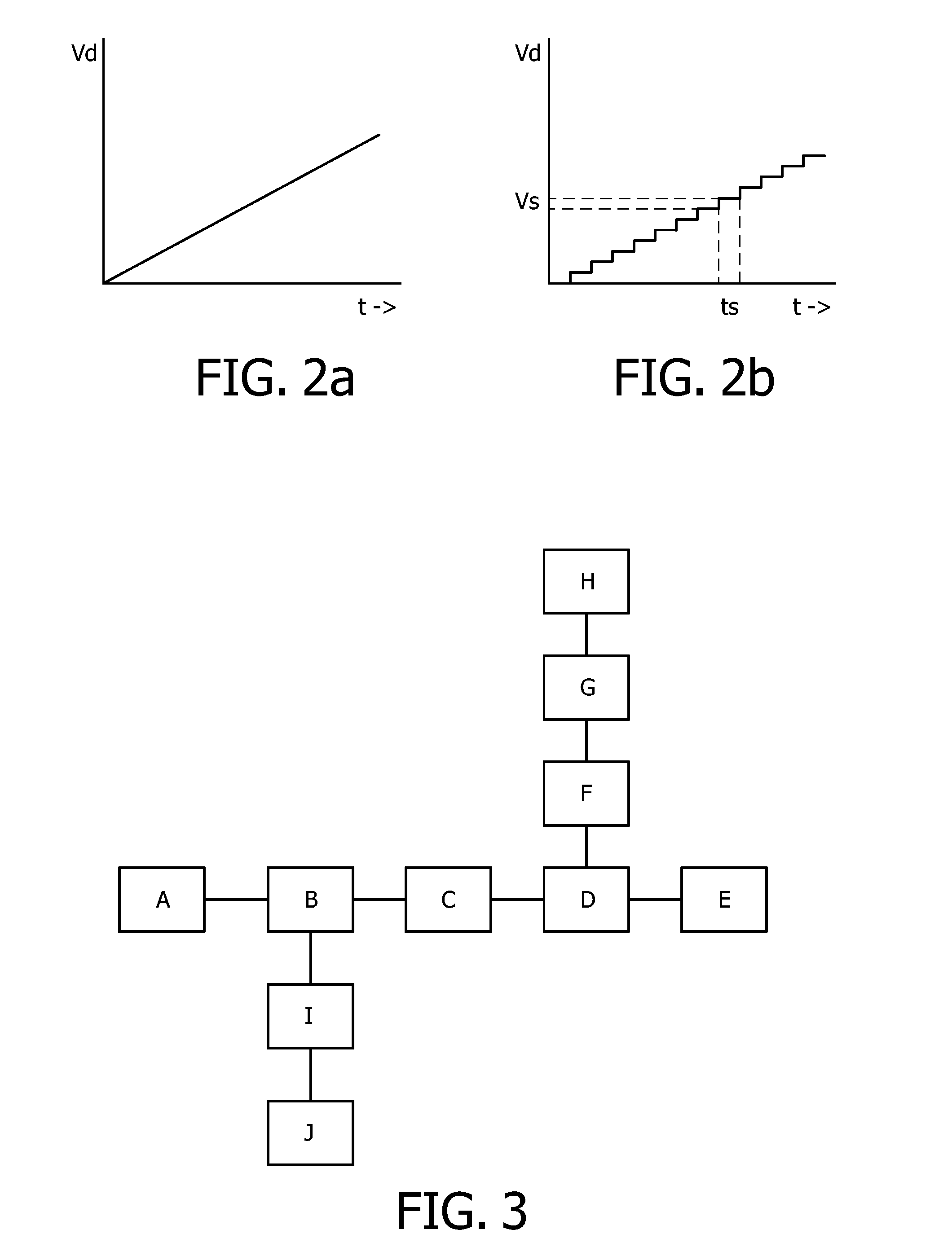
[0044]The method of the invention could be worked as follows. A device is selected, e.g. randomly. Suppose a device is selected which will (later) turn out to be the device denoted F in the FIG. 1. In principle, any other device could also be the selected device. This will be discussed further with reference to FIG. 3

[0045]As a first step, a synchronization of all devices A-I is carried out. Thereto, the selected d...


PUM


Abstract

The invention discloses a method to determine a relative position of devices in a network, and to a network of devices for carrying out the method. In a network with a power cable (10) connected to a plurality of devices (A-I), one needs to know the physical position thereof in order be able to control them efficiently. This used to be done manually, but the present method proposes to select a device to send a detection signal with increasing amplitude across the network, and to measure the time each of the remaining devices detects the detection signal. Due to signal losses in the network, a more remote device will show a longer detection time. Collecting the various detection times enable a control unit (12) to determine the relative position of all, or at least part of, the devices (A-I).

Description

FIELD OF THE INVENTION[0001]The invention relates to a method to determine a relative position of devices in a network, and to a network of devices for carrying out the method.BACKGROUND OF THE INVENTION[0002]In more or less complex systems with several controllable devices, such as larger lighting systems in buildings, along roads etc., it is often desirable to bind a device, e.g. a lamp with a switch, into that system. This allows for example a remote control of the devices. Nowadays, devices may be used that have their own unique ID. Still it is necessary to know “where” those devices are located in the system for an operator or control unit to be able to control the right device.[0003]US Application No. 2003 / 0222603 discloses an system and method for correlating between the location of a component and its ID. In one embodiment, each component is operated separately, and an operator records the physical coordinates in each case. This is very time consuming, and needs at least one...

Claims


Application Information

Patent Timeline
Patent Type & Authority Applications(United States)
IPC IPC(8): H04L12/28
CPCH04L41/12H05B37/0254H05B47/18
Inventor STEVENS, HENDRIK
Owner KONINKLIJKE PHILIPS ELECTRONICS NV
Why Eureka
Try Eureka