Line sorter

a sorter and line sorting technology, applied in the direction of conveyor parts, non-mechanical conveyors, transportation and packaging, etc., can solve the problems of limiting the use amount of energy and the generated acoustic noise when operating the system, needing a large amount of energy to operate, and generating acoustic noise, etc., to achieve the effect of reducing one, reducing one, and eliminating on

Active Publication Date: 2019-08-13
BEUMER GRP AS
View PDF30 Cites 2 Cited by
  • Summary
  • Abstract
  • Description
  • Claims
  • Application Information

AI Technical Summary

Benefits of technology

[0006]It may be seen as an object of the present invention to provide an improved line sorter. Preferably, the invention alleviates, mitigates or eliminates one or more of the above or other disadvantages singly or in any combination.
[0007]In particular, it may be seen as an object of the invention to provide a line sorter with a reduced need for energy input at a given sorting capacity.

Problems solved by technology

Thus, e.g. a substantial amount of energy may be used by the system and some acoustic noise may also be generated.
Furthermore, due to a need for high performance, e.g. in terms of number of sorted items per hour, but also including a need for extreme reliability, each part of the system must be engineered to suit these needs, while limiting the used amount of energy and the generated acoustic noise when operating the system.
Some line sorter systems may have had a high reliability, but may then have been in need of a high amount of energy to operate.
Other systems may have needed a low amount of energy to operate, but then suffered from a high amount of generated acoustic noise and / or suffered from having a low capacity measured in its ability to sort a given number of items per hour.
Some systems suffer from a too high initial cost and / or a too high cost of maintaining the systems and / or do not provide numerous years of hassle free operation.

Method used


Image

  • Line sorter
  • Line sorter
  • Line sorter

Examples


Embodiment Construction

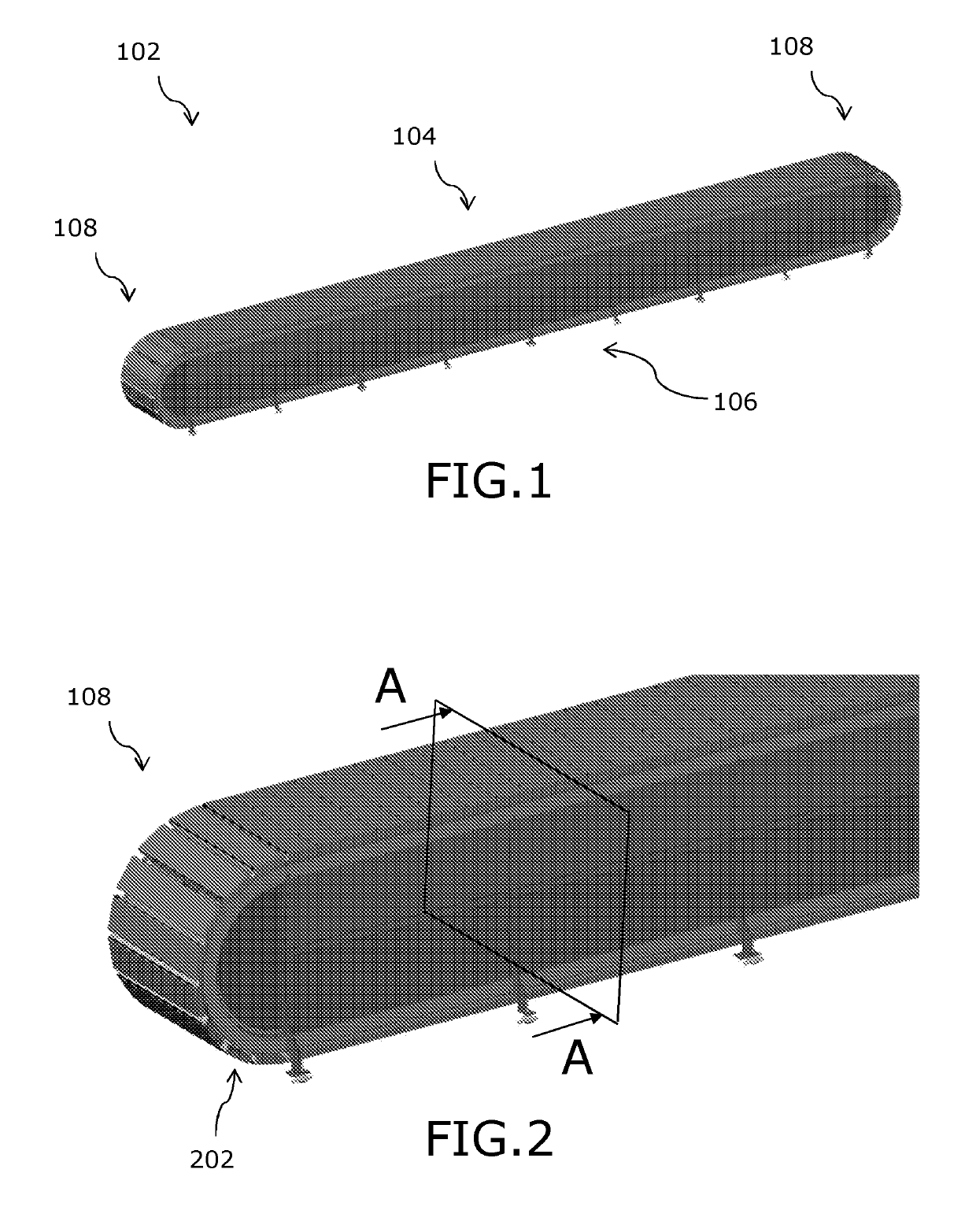
[0046]FIG. 1 shows a line sorter 102 in a perspective view. The figure does not show any inductions or discharges or other peripherals or parts of the system, such as a control system. The line sorter 102 is adapted for sorting items of various shapes, sizes and weights, such as postal parcels or airport baggage.

[0047]The line sorter includes an upper track section 104 and a lower track section 106. The upper section and the lower section are connected to, or otherwise operably positioned at, end track sections 108. There is one end track section at each of the two ends of the line sorter. At least one position at the lower track section and / or the upper track section is dedicated induction of items onto the line sorter 102, such as by an induction or conveyor (not shown). Although also not shown, a plurality of discharges or chutes is normally provided along the lower track section and / or the upper track section, and for sorting one or more items into their respective discharge. Du...


PUM


Abstract

The invention relates to a line sorter for sorting items of various shapes, sizes and weights, in particular postal parcels or airport baggage. The invention is particularly related to the propulsion system (304, 306, 406) for the sorter. It may be seen as an object of the invention to provide a line sorter with a reduced need for energy input at a given sorting capacity. It is disclosed that a closed loop chain including sorting carts or slats (302) is provided with couplings (312) and is provided for moving along line sorter track sections. The linear synchronous motor propulsion system is provided for moving said closed loop chain, and a gap between adjacent permanent magnets (306) is the same or substantially the same between each of the permanent magnets.

Description

FIELD OF THE INVENTION[0001]The invention relates to a line sorter for sorting items of various shapes, sizes and weights, in particular postal parcels or airport baggage. The invention is particularly related to a propulsion system for moving parts of the sorter and how to implement this in a most effective manner.BACKGROUND OF THE INVENTION[0002]A sorter is a device able to sort items according to their identification and by loading or inducting the items onto the sorter and unloading, i.e. discharging them, at a discharge in accordance with the identification and thus into one or more discharges dedicated the items.[0003]Sorters of the type as the present invention are typically suited for sorting several thousands of items per hour. Thus, e.g. a substantial amount of energy may be used by the system and some acoustic noise may also be generated. Furthermore, due to a need for high performance, e.g. in terms of number of sorted items per hour, but also including a need for extrem...

Claims


Application Information

Patent Timeline
Patent Type & Authority Patents(United States)
IPC IPC(8): B65G47/94B65G47/54B65G54/02B65G47/96B65G17/06B65G23/23
CPCB65G47/94B65G17/06B65G54/02B65G47/54B65G47/96B65G23/23
Inventor LYKKEGAARD, UFFE
Owner BEUMER GRP AS
Why Eureka
Try Eureka