Split cycle engine with crossover shuttle valve

a technology of shuttle valve and split cycle engine, which is applied in the direction of valve arrangement, combustion engine, machine/engine, etc., can solve the problems of reducing engine efficiency and revealing how to effectively

Active Publication Date: 2019-08-13
TOUR ENGINE INC
View PDF58 Cites 6 Cited by
  • Summary
  • Abstract
  • Description
  • Claims
  • Application Information

AI Technical Summary

Benefits of technology

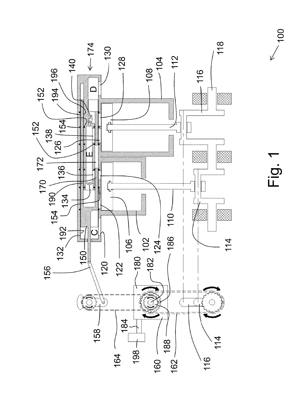
[0016]According to some embodiments the combustion chamber structure may define a combustion chamber having a spherical or an oval shape or a circular or oval cross-section. According to some embodiments the combustion chamber structure may have an external cylindrical shape dimensioned to fit inside the cylindrical sleeve, so that the cylindrical sleeve may slide along the valve cylinder between an internal surface of the valve cylinder and an external surface of the combustion chamber structure. According to some embodiments the cylindrical sleeve is dimensioned and configured to slide along the valve cylinder, maintaining high pressure sealing between the valve cylinder and the cylindrical sleeve and between the cylindrical sleeve and the combustion chamber structure. Maintaining sealing here means effective prevention or reduction (posing resistance) to lateral flow of a fluid along the cylinders between the valve cylinder and the cylindrical sleeve and between the cylindrical sleeve and the combustion chamber structure. In some exemplary embodiments, sealing rings, substantially similar to sealing rings between a piston and a cylinder in a conventional ICE, are used for maintaining high pressure sealing.
[0026]According to some embodiments the compression chamber has a different maximum volume from the maximum volume of the expansion chamber. According to some embodiments the split-cycle ICE utilizes a different compression ratio than an expansion ratio. In some known examples of ICEs, in order to increase fuel efficiency, the compression cylinder is of smaller internal volume than the expansion cylinder. In other known examples, in order to increase the power output of the engine, the compression cylinder is of greater internal volume than the expansion cylinder. A compression cylinder smaller than the expansion cylinder results in less fuel being consumed per unit work, and hence higher fuel efficiency, but also results in lower power output. According to such examples, an engine may thus be either fuel efficient or it may have high power output, but it cannot provide both.
[0033]According to some embodiments the first cylinder is smaller than the second cylinder, that is to say, the maximum internal volume of the first chamber is smaller than the maximum internal volume of the second chamber. According to some embodiments the bi-directional engine further comprises an auxiliary combustion chamber fluidly connectable, through an auxiliary valve, to the combustion chamber. According to some embodiments, in the first mode of operation of the engine, the auxiliary combustion chamber is disconnected from the combustion chamber by the auxiliary valve, and therefore out of use. In the second mode of operation, where the compression chamber is larger than in the first mode, the auxiliary combustion chamber is fluidly connected to the combustion chamber by the auxiliary valve, thereby increasing the total volume wherein combustion occurs, and thereby accommodating combustion of higher volume of working fluid while maintaining the compression ratio below a suitable value.

Problems solved by technology

The references described above fail to disclose how to effectively govern the transfer of the working fluid in a timely manner and without pressure loss from the compression cylinder to the power cylinder, using a valve system that is durable with high level of sealing.
In addition, the separate cylinders disclosed in these references are typically connected by a transfer valve or intermediate passageway (connecting tube) of some sort that yields a substantial volume of “dead space” between cylinders, reducing the engine efficiency.

Method used


Image

  • Split cycle engine with crossover shuttle valve
  • Split cycle engine with crossover shuttle valve
  • Split cycle engine with crossover shuttle valve

Examples


Embodiment Construction

[0154]The principles, uses and implementations of the teachings herein may be better understood with reference to the accompanying description and figures. Upon perusal of the description and figures present herein, one skilled in the art is able to implement the teachings herein without undue effort or experimentation. In the figures, like reference numerals refer to like parts throughout.

[0155]In-Line Configuration of a Split-Cycle Engine

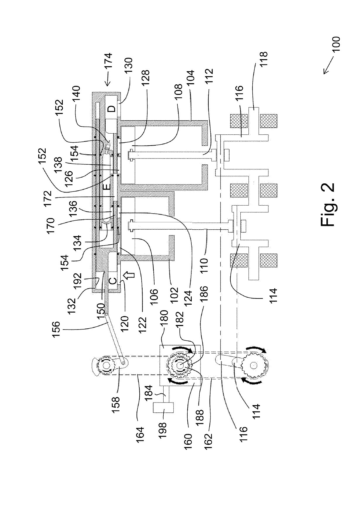
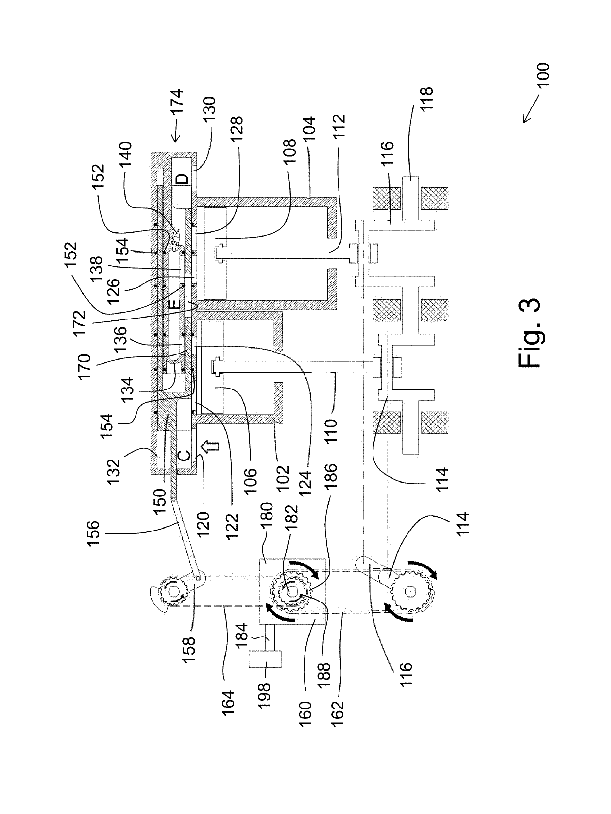
[0156]Referring to FIGS. 1-17, in accordance with one embodiment, an in-line configuration of a split-cycle engine 100 includes: a first cylinder 102, a second cylinder 104, a first piston 106, a second piston 108, a first chamber A defined between first cylinder 102 and first piston 106 (shown in FIGS. 4-14, 20-30, 36-46, 52-62), and a second chamber B defined between second cylinder 104 and second piston 108 (shown in FIGS. 4-14, 20-30, 36-46, 52-62). The split-cycle engine also includes a first piston connecting rod 110, a second piston connect...


PUM


Abstract

A split-cycle internal combustion engine (ICE) is provided, comprising a compression cylinder, an expansion cylinder and a crossover valve having a valve cylinder housing inside a shuttle and a combustion chamber structure defining a combustion chamber. The shuttle is configured to perform reciprocating motion inside the valve cylinder synchronously with a compression piston and an expansion piston, thereby alternatingly fluidly coupling and decoupling the combustion chamber with the compression cylinder and with the expansion cylinder, selectively. Sealing rings positioned between the valve cylinder and the shuttle prevent gas leaks between them during the reciprocating motion. In some embodiments, a phase shift between the pistons may be set or varied by a piston phase transmission gear. A bi-directional fluid flow split-cycle internal combustion engine (ICE) is also provided having a first cylinder, a second cylinder, a combustion chamber and a single crossover valve fluidly communicating them.

Description

CROSS-REFERENCE TO RELATED APPLICATIONS[0001]This application is a U.S. National Stage of International Application No. PCT / IL2016 / 050061 filed Jan. 19, 2016 which claims priority to U.S. Provisional Application No. 62 / 104,885 filed Jan. 19, 2015; No. 62 / 138,435 filed Mar. 26, 2015; and No. 62 / 197,582 filed Jul. 28, 2015. The contents of these applications are incorporated herein by reference in their entirety.FIELD OF THE INVENTION[0002]Aspects of the invention, in some embodiments thereof, relate to split-cycle Internal Combustion Engines (ICE), and more particularly, but not exclusively, to split-cycle engines having a crossover valve regulating fluid flow between a compression chamber and an expansion chamber.BACKGROUND OF THE INVENTION[0003]Conventional four-stroke internal combustion engines include one or more cylinders. Each cylinder includes a single piston that performs four strokes, commonly referred to as the intake, compression, combustion / power / expansion, and exhaust s...

Claims


Application Information

Patent Timeline
Patent Type & Authority Patents(United States)
IPC IPC(8): F01L5/04F01L7/02F02B33/22F02B33/44F02B41/06
CPCF02B33/22F01L5/045F02B41/06F02B33/44F01L7/02
Inventor TOUR, GILADTOUR, ODEDTOUR, HUGO BENJAMIN
Owner TOUR ENGINE INC
Why Eureka
Try Eureka