Slide block mechanism for semi-automatic pistols

a semi-automatic pistol and slide block technology, applied in firearms, weapons, weapons types, etc., can solve the problems of inability to mitigate the noise created by the mechanical action of the pistol, serious hearing damage to the user and surrounding persons, and the discharging of semi-automatic pistols. achieve the effect of preventing the reciprocating slide and eliminating the sound of the action

Active Publication Date: 2019-08-13
NEVADA CARTRIDGE CO LLC
View PDF4 Cites 6 Cited by
  • Summary
  • Abstract
  • Description
  • Claims
  • Application Information

AI Technical Summary

Benefits of technology

[0005]The slide block mechanism of this invention effectively allows the user to selectively switch a semi-automatic pistol to a single shot pistol. When engaged, the slide block mechanism prevents the reciprocation of the slide, eliminating the sound of the action. When disengaged, the slide block mechanism does not affect the operation of the pistol allowing the slide to reciprocate freely. The slide block mechanism also does not alter or effect the operation of the fire control mechanism of the pistol and is completely independent of the pistol's traditional slide stop and fire control assemblies. The slide block mechanism may be integrated into many conventional semi-automatic pistol designs, with minor modifications to the slide and frame, and may co-opt or use the internal pins and components of the pistol's fire control mechanism to support the pivoting slide lever.

Problems solved by technology

The discharge of semi-automatic pistols creates extremely high levels of noise.
The report of a pistol can cause serious hearing damage to the user and surrounding persons.
The noise created by the mechanical action of the pistol cannot be mitigated unless the slide is physically prevented from reciprocating upon discharge.
Heretofore, semi-automatic pistols generally include slide stop mechanisms that lock the slide to the rear when the magazine is empty, but have no mechanism for physically locking the slide in battery, i.e. the forward closed position, and preventing the slide from reciprocating on discharge.

Method used


Image

  • Slide block mechanism for semi-automatic pistols
  • Slide block mechanism for semi-automatic pistols
  • Slide block mechanism for semi-automatic pistols

Examples


Embodiment Construction

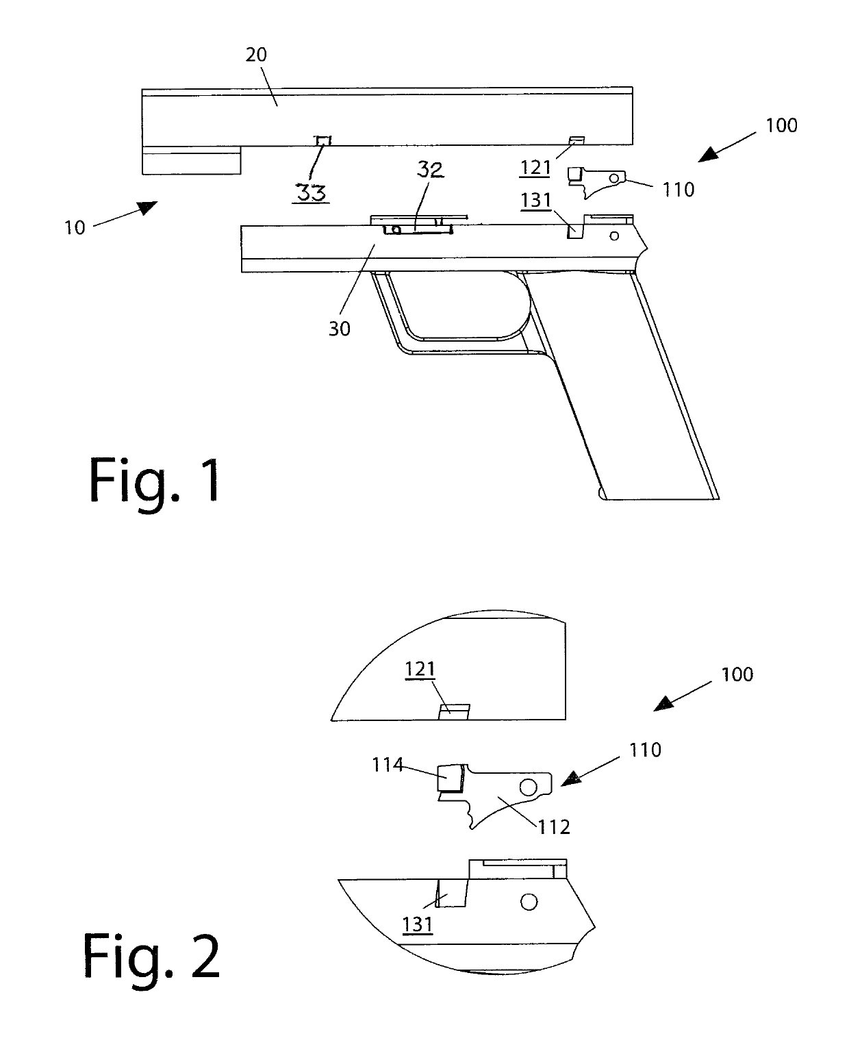
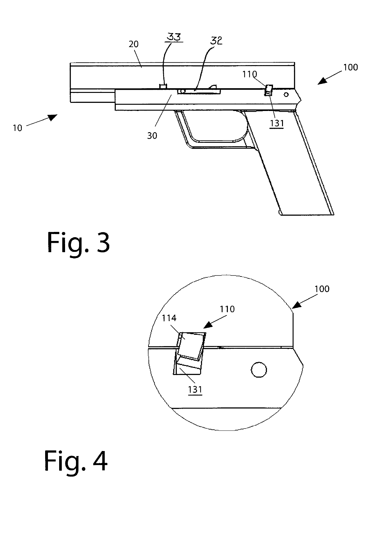
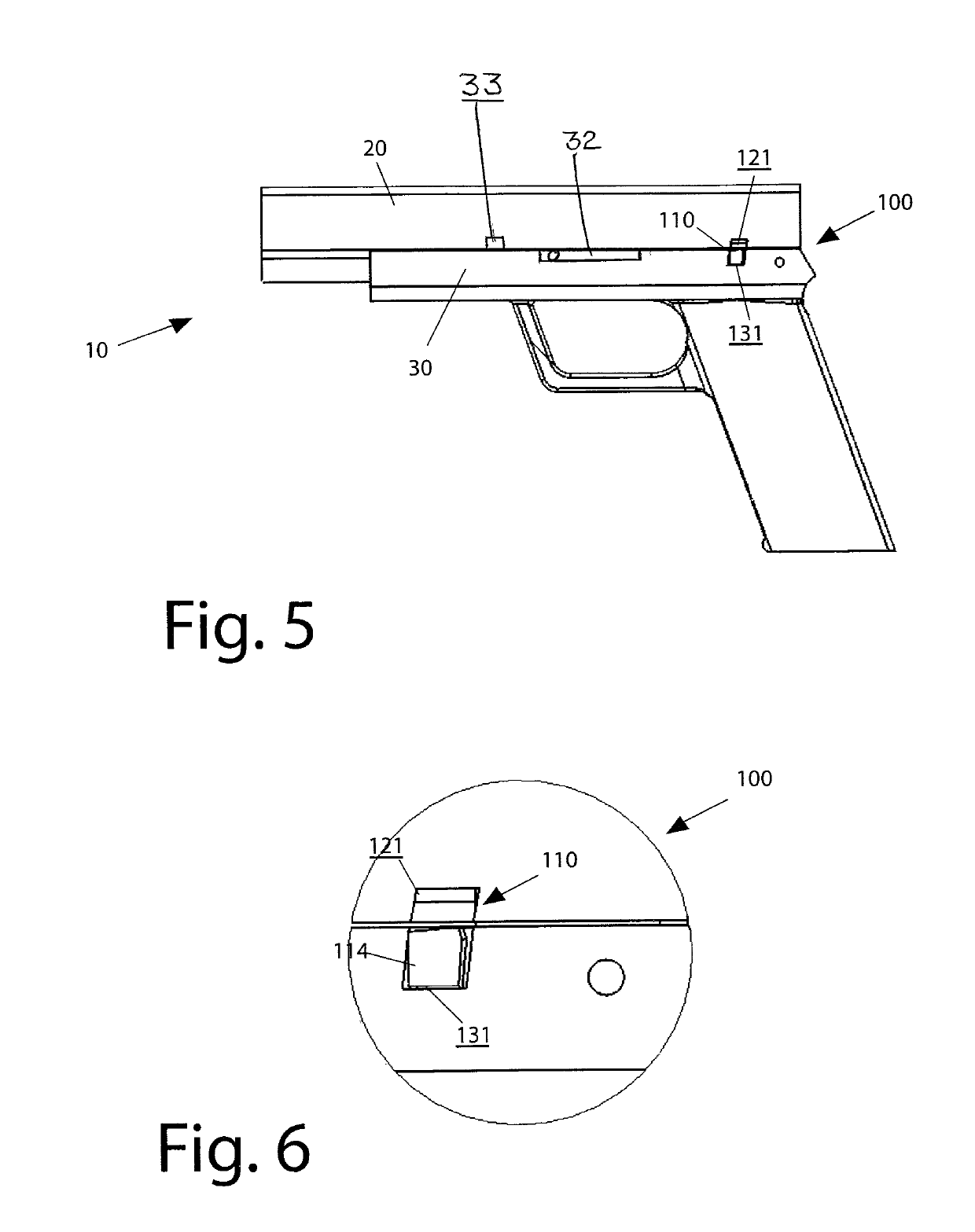
[0031]In the following detailed description of the preferred embodiments, reference is made to the accompanying drawings that form a part hereof, and in which is shown by way of illustration specific preferred embodiments in which the invention may be practiced. These embodiments are described in sufficient detail to enable those skilled in the art to practice the invention, and it is understood that other embodiments may be utilized and that logical, structural, mechanical, electrical, and chemical changes may be made without departing from the spirit or scope of the invention. To avoid detail not necessary to enable those skilled in the art to practice the invention, the description may omit certain information known to those skilled in the art. The following detailed description is, therefore, not to be taken in a limiting sense, and the scope of the present invention is defined only by the appended claims.

[0032]The slide lock mechanism of this invention helps minimize the sound ...


PUM


Abstract

A slide block mechanism for a semi-automatic pistol that locks the slide in battery and prevents the slide from reciprocating when the pistol is discharged. The slide block mechanism consists of a pair of aligned notches formed in the bottom edge of the slide and the top of the frame, and a pivoting slide block lever mounted to the frame that selectively seats within either of the aligned notches. The slide block lever can be manually switched to engage and disengage the slide block mechanism and is independent of the fire control and slide stop assemblies. The slide block lever has a protrusion that seats within the slide notch when engaged to prevent the slide from moving rearward and seats within the frame notch when disengaged for allowing normal operation of the slide.

Description

[0001]This is a continuation-in-part of pending U.S. patent application Ser. No. 16 / 040,202 filed on Jul. 19, 2018, which claims the benefit of U.S. Provisional Application No. 62 / 534,431 filed Jul. 19, 2017.[0002]This invention relates to semi-automatic pistols, and in particular a slide block mechanism for blocking the slide in battery and preventing the reciprocation of the slide when the pistol is discharged.BACKGROUND OF THE INVENTION[0003]The discharge of semi-automatic pistols creates extremely high levels of noise. The report of a pistol can cause serious hearing damage to the user and surrounding persons. The sound created by the discharge of a pistol is the result of the escaping propellent gas the hyper sonic travel of the projectile, and the mechanical action, i.e. the reciprocation of the slide of the semi-automatic pistols. Sound suppressors, often inaccurately referred to as “silencers” generally baffle and dampen the sounds of the escaping propellent gas. The use of ...

Claims


Application Information

Patent Timeline
Patent Type & Authority Patents(United States)
IPC IPC(8): F41A3/42
CPCF41A3/42F41A21/30F41C3/00
Inventor HOPKINS, EDWARD CAMERON NINDSALASSA, CLAUDIO
Owner NEVADA CARTRIDGE CO LLC
Why Eureka
Try Eureka