Welding wire feeder bus control system and method

Active Publication Date: 2019-08-20
ILLINOIS TOOL WORKS INC
View PDF109 Cites 0 Cited by
  • Summary
  • Abstract
  • Description
  • Claims
  • Application Information

AI Technical Summary

Benefits of technology

[0006]In one embodiment, a welding wire feeder includes a welding wire feed drive configured to drive welding wire towards a welding application and wire feed control circuitry coupled to the welding wire feed drive. The wire feed control circuitry is also configured to control the drive of welding wire towards the welding application. The welding wire feeder also includes power conversion circuitry configured to receive input power and to convert the input power to welding output suitable for a welding application. The power conversion circuitry includes power storage circuitry configured to store energy and to discharge at le

Problems solved by technology

Unfortunately, lengthy power cables between a welding power source and a welding applic

Method used


Image

  • Welding wire feeder bus control system and method
  • Welding wire feeder bus control system and method
  • Welding wire feeder bus control system and method

Examples


Embodiment Construction

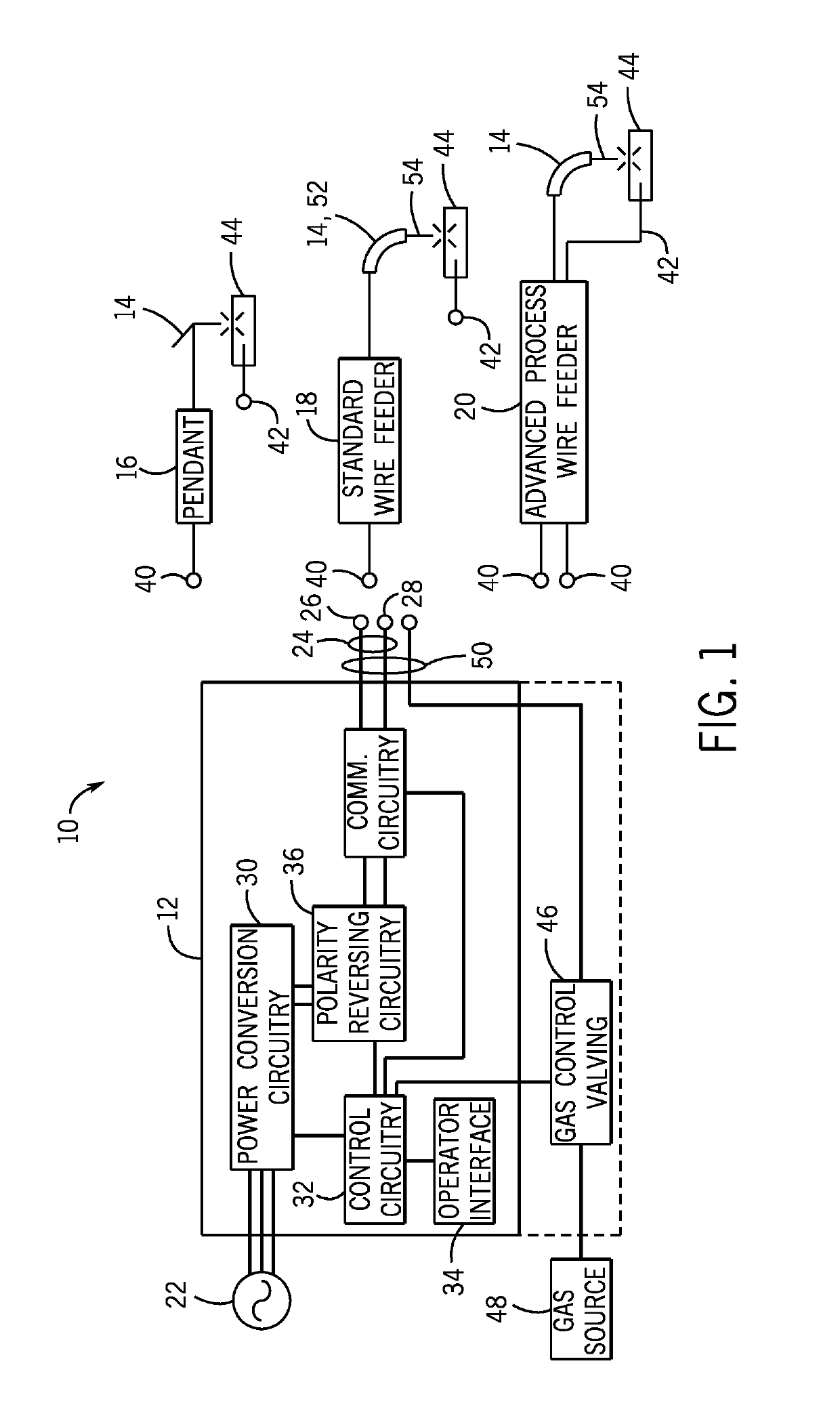
[0028]FIG. 1 is a block diagram of an embodiment of a welding system 10 which powers a welding application. As illustrated, the welding system 10 includes a welding power source 12 and a coupled welding torch 14. The welding power source 12 supplies input power to the welding torch 14. The welding torch 14 may be a torch configured for stick welding, tungsten inert gas (TIG) welding, or gas metal arc welding (GMAW), based on the desired welding application. In some embodiments, the welding power source 12 supplies input power to a pendant 16 coupled to a torch 14 configured for stick welding or TIG welding. The operator supplies the filler metal, if any, for stick or TIG welding. The pendant 16 may be configured to control the power source 12 and / or notify the operator of welding parameters. In other embodiments, the welding power source 12 supplies input power to a standard wire feeder 18. The standard wire feeder 18 supplies the input power and filler metal to a welding torch 14 c...


PUM

PropertyMeasurementUnit
Timeaaaaaaaaaa
Poweraaaaaaaaaa
Currentaaaaaaaaaa

Abstract

A welding wire feeder includes a wire feed drive and wire feed control circuitry coupled to the wire feed drive to control the drive of welding wire towards the welding application. The welding wire feeder includes power conversion circuitry configured to receive input power and to convert the input power to welding output suitable for a welding application, output voltage sensors configured to measure output voltage, output current sensors configured to measure output current, and control circuitry coupled to the power conversion circuitry and to the output voltage and current sensors. The power conversion circuitry includes power storage circuitry configured to store energy and to discharge at least a portion of the stored energy during an overdraw event. The control circuitry is configured to control the output current during the overdraw event to maintain a stored energy value of the power storage circuitry greater than a desired minimum energy value.

Description

CROSS-REFERENCE TO RELATED APPLICATION[0001]This application hereby claims priority to and the benefit of U.S. Provisional Application Ser. No. 61 / 907,835, entitled “WELDING WIRE FEEDER BUS CONTROL SYSTEM AND METHOD,” filed Nov. 22, 2013. This application also is a continuation-in-part of U.S. application Ser. No. 13 / 837,890, entitled “WELDING WIRE FEEDER POWER APPLICATION SYSTEM AND METHOD,” filed Mar. 15, 2013, which claims priority to and the benefit of U.S. Provisional Application Ser. No. 61 / 657,504, entitled “WELDING WIRE FEEDER POWER APPLICATION SYSTEM AND METHOD,” filed Jun. 8, 2012. Each of these above listed U.S. Applications are hereby incorporated by reference in their entireties for all purposes.BACKGROUND[0002]The invention relates generally to welding systems, and, more particularly, to controlled waveform welding wire feeder systems and methods.[0003]Welding systems support a variety of processes, such as metal inert gas (MIG) welding, tungsten inert gas (TIG) weldin...

Claims


Application Information

Patent Timeline
IPC IPC(8): B23K9/10B23K9/12
CPCB23K9/1012B23K9/125B23K9/124B23K9/1043
Inventor BEISTLE, EDWARD G.
Owner ILLINOIS TOOL WORKS INC
Why Eureka
Try Eureka