Integrated motor drive system for motor driven yarn feed attachments

a technology of motor drive and yarn feed, which is applied in the direction of automatic machines, embroidering machines, textiles and paper, etc., can solve the problems of increasing the cost of machine manufacture and setup, increasing the cost of use of tube banks, and reducing the precision of the effect of the machin

Active Publication Date: 2012-06-19
CARD MONROE
View PDF88 Cites 18 Cited by
  • Summary
  • Abstract
  • Description
  • Claims
  • Application Information

AI Technical Summary

Benefits of technology

[0009]Briefly described, the present invention generally relates to a yarn feed system or pattern yarn feed attachment that is removably mounted on a tufting machine and is adapted to feed a series of yarns individually to each of the needles of the tufting machine. The feeding of the individual yarns to each needle is independently controlled by the yarn feed system to provide enhanced precision and control as needed or desired to form tufts of yarn in a backing material being passed through the tufting machine according to programmed carpet pattern instructions. The yarn feed system of the present invention generally comprises a yarn feed unit that can be constructed as a standardized, self-contained unit or attachment that can be releasably mounted to and / or removed from the tufting machine as a unit, and enables multiple yarn feed units to be mounted to the tufting machine in series as needed depending on the number of needles in the tufting machine.
[0011]A control system is provided, including a series of yarn feed controllers support mounted within the housing of the yarn feed unit. Each of the yarn feed controllers can be linked to an associated yarn feed drive motor to provide pattern / operating instructions thereto. Each yarn feed controller generally can include a controller board or processor module that typically will comprise a primary control processor mounted on the board and a motor controller or drive, each connected or linked to the primary control processor and to an associated drive motor. A secondary control processor further can be provided to provide for backup and redundancy for each yarn feed controller to increase or enhance reliability thereof. Each motor controller generally controls at least one of the drive motors of the yarn feed devices in accordance with control instructions provided by the primary and / or secondary control processors.
[0012]Alternatively, each of the motor controllers of the yarn feed controllers can be directly integrated with an associated drive motor, each controller being directly coupled to and mounted with its associated motor to form an integrated yarn feed drive unit or device. The integrated motor controllers can directly control their drive motors in accordance with control instructions from the control system, such as being provided by the primary and / or secondary control processors, and / or received from the tufting machine controller for directly controlling its associated yarn feed motor, and by being integrated directly together with their associated motors, enable increased reliability from the motors for driving multiple, i.e., 3, 4, 5 or more, ends of yarns. Each of the integrated yarn feed controllers also generally will be directly linked to the control system processor(s) by a communications network cable over which it can receive pattern control instructions from and provide direct feedback to the control processor(s) of the control system regarding the current operation of the drive motors being controlled by each motor controller.
[0015]The yarn feed unit of the present invention thus provides individualized control of the feeding of each of a series of yarns to each of the needles of the tufting machine according to programmed pattern instructions to form a desired pattern. The yarn feed unit of the present invention further enables the manufacture of standardized yarn feed attachments or units, including the use of yarn feed devices having integrated yarn feed controllers and drive motors, that can be manufactured, tested, stored in inventory, and thereafter removably installed on a tufting machine without requiring the custom design and installation of such a pattern attachment, and without requiring a costly and time-consuming set-up of the machine and tube bank array therefor. In addition, the housing of the yarn feed unit can be formed with a substantially open design, and the yarn feed unit can include a series of fans and heat sinks being provided for the yarn feed controllers to promote the efficient dissipation of heat from the yarn feed unit for the efficient and reliable operation of the electronic components thereof.

Problems solved by technology

A significant problem, however, that exists with the use of such traditional pattern attachments and even with more recently developed scroll type pattern attachments such as disclosed in U.S. Pat. No. 6,244,203, which discloses a servo-motor controlled scroll type pattern attachment for a tufting machine, has been the requirement for tube banks that extend from the pattern attachment feed rolls at varying lengths across the tufting machine for feeding the yarns from the pattern attachment feed rolls to the needles.
The problem with such tube banks generally has been that the yarns passing through the longer tubes are typically subjected to increased drag or friction as they are passed along the increased length of their tubes, such that it has been difficult to achieve high amounts of precision and responsiveness to changes in the pattern across the width of the carpet.
The use of the tube banks further adds a significant cost both in terms of manufacture and set up of the machines, as well as significantly increasing the complexity of operation of the tufting machines.
However, as the number of yarn feed rolls and number of motors associated therewith for driving such individual yarn feed rolls is increased, there is likewise a corresponding increase in the costs of such pattern attachments.
In addition, increasing the number of motors and feed rolls further increases the complexity of manufacturing and set up of such attachments as a part of a tufting machine when the machine is installed in the field.

Method used


Image

  • Integrated motor drive system for motor driven yarn feed attachments
  • Integrated motor drive system for motor driven yarn feed attachments
  • Integrated motor drive system for motor driven yarn feed attachments

Examples


Embodiment Construction

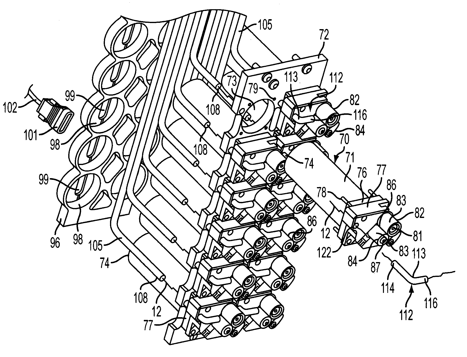
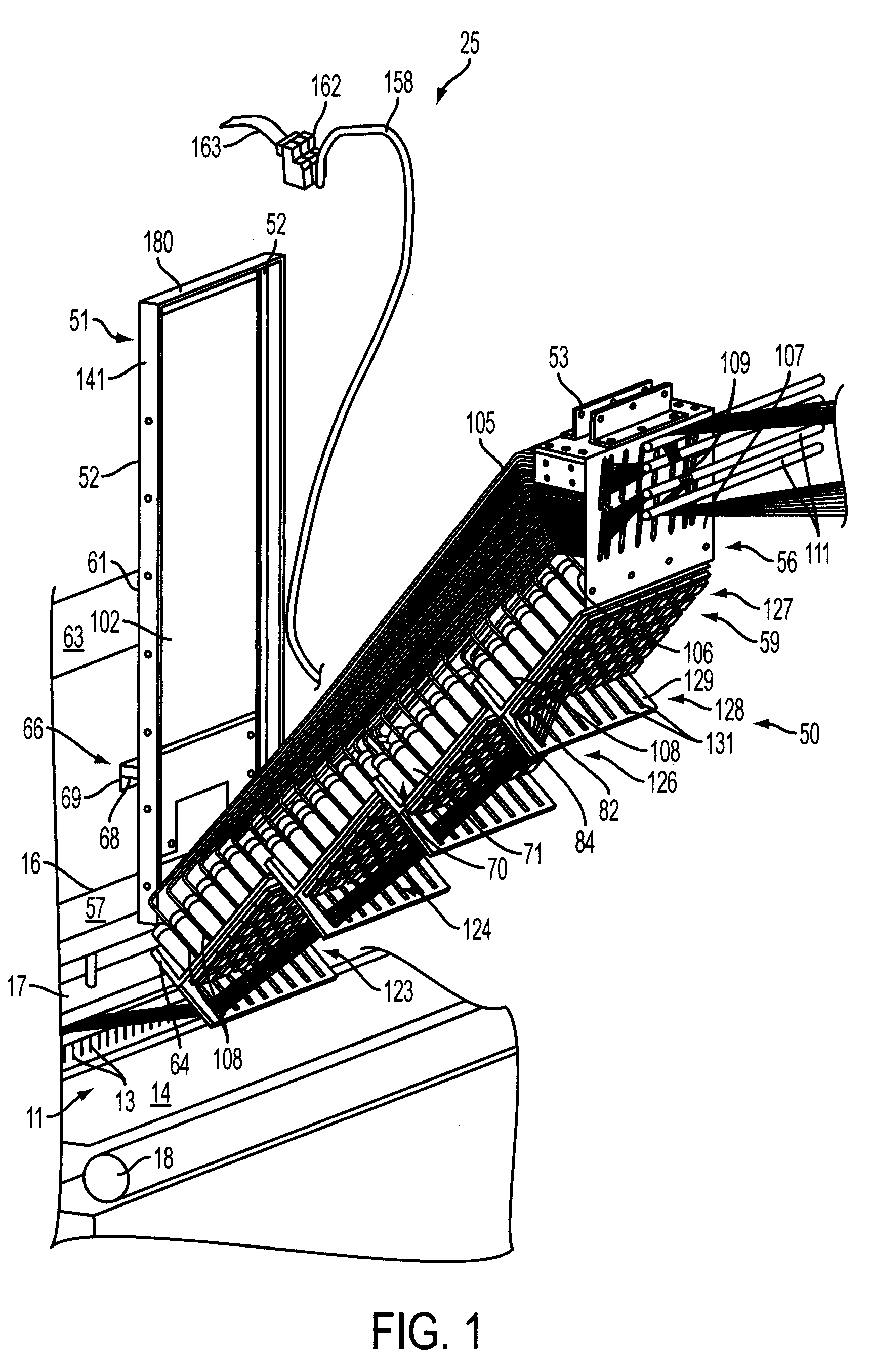
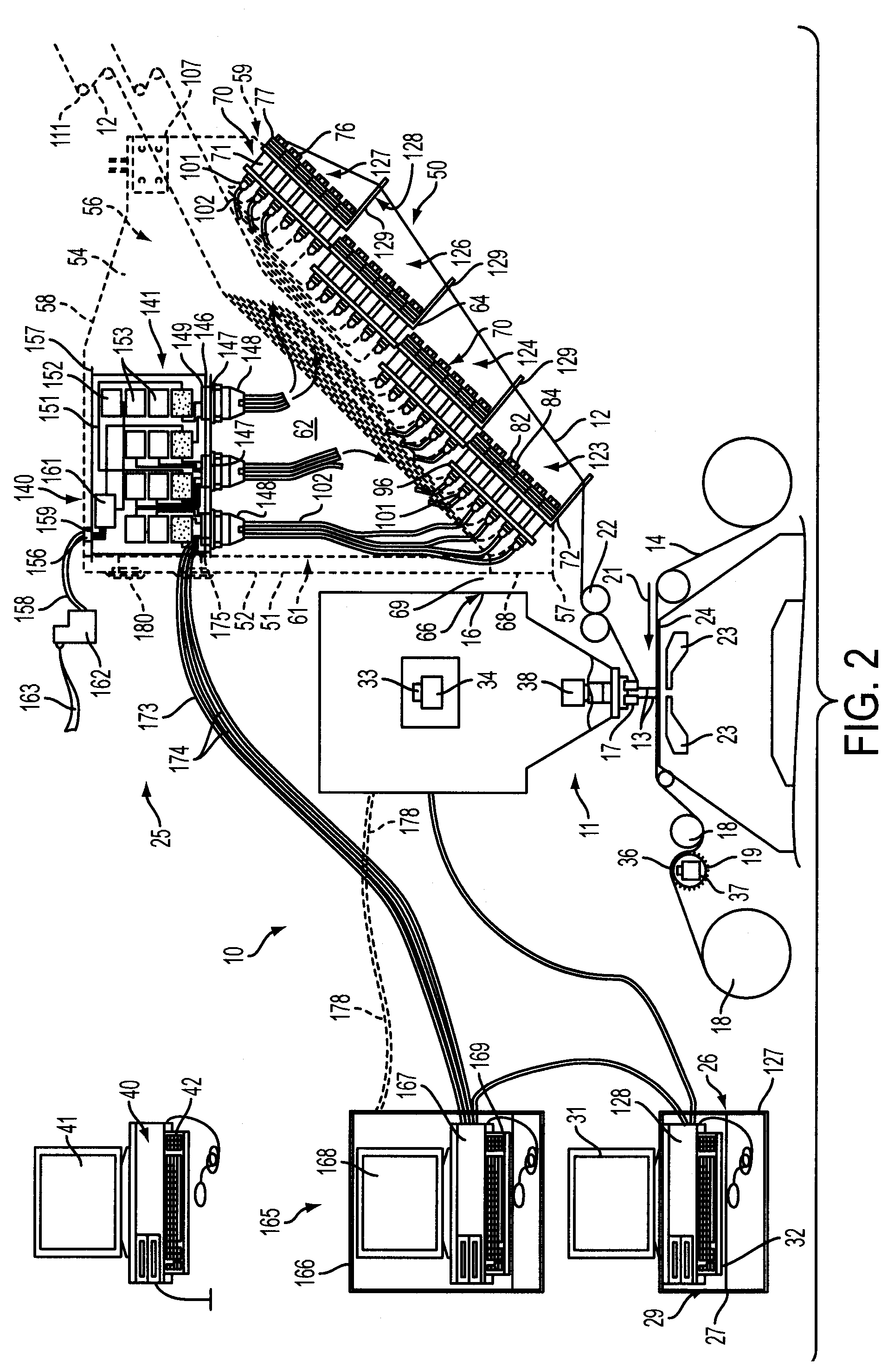
[0030]Referring now in greater detail to the drawings in which like numerals indicate like parts throughout the several views, FIGS. 1-7 generally illustrate example embodiments of the yarn feed control system or yarn feed pattern attachment 10 of the present invention, which is releasably mountable to a tufting machine 11 (FIGS. 1, 2) for controlling the feeding of individual yarns 12 to the needles 13 of the tufting machine 11. The yarn feed system of the present invention enables the feeding of individual yarns to each needle to be independently controlled to enable greater precision and control in the formation of tufts of yarn in a backing material 14 passing through the tufting machine and beneath the needles 13 in order to form programmed or desired carpet patterns.

[0031]As indicated in FIG. 2, the tufting machine 11 generally will comprise a conventional tufting machine such as disclosed in U.S. Pat. No. 5,979,344, having a frame 16 on which is supported a machine drive or m...


PUM


Abstract

A yarn feed system, enabling the control of individual yarns to the needles of a tufting machine, and which system can be manufactured as a substantially standardized unit or attachment that can be removably mounted to a tufting machine. The yarn feed unit includes a series of yarn feed devices each including a drive motor for feeding one or more selected yarns to the needles of the tufting machine, and a series of yarn feed controllers integrated with each yarn feed drive motor for monitoring and controlling the operation of the yarn feed devices to control the feeding of the yarns to the needles according to programmed pattern instructions.

Description

CROSS-REFERENCE TO RELATED APPLICATIONS[0001]This application claims the benefit of U.S. Provisional Patent Application No. 61 / 236,694, filed Aug. 25, 2009.INCORPORATION BY REFERENCE[0002]U.S. Provisional Application No. 61 / 236,203, which was filed on Aug. 24, 2009, is hereby incorporated by reference for all purposes as if presented herein in its entirety.FIELD OF THE INVENTION[0003]The present invention generally relates to carpet tufting machines and in particular to yarn feed systems and / or pattern attachments including a series of yarn feed devices or drive mechanisms for controlling the feeding of individual yarns to the needles of a tufting machine.BACKGROUND OF THE INVENTION[0004]In the carpet-tufting field, there is considerable emphasis placed on developing new, eye-catching carpet patterns to keep up with changing consumer tastes and increased competition in the marketplace. With the introduction of computer controls for tufting machines, as disclosed in U.S. Pat. No. 4,8...

Claims


Application Information

Patent Timeline
Patent Type & Authority Patents(United States)
IPC IPC(8): D05C15/00
CPCD05C15/18D05C15/34
Inventor CHRISTMAN, JR., WILLIAM M.
Owner CARD MONROE
Why Eureka
Try Eureka