Press

a technology of pressing machine and pressing plate, which is applied in the direction of forging press, forging/pressing/hammering apparatus, shape safety device, etc., can solve the problems of reducing accuracy, local wear of balls and/or ball grooves, and describing the problems of conventional electric presses

Inactive Publication Date: 2007-11-13
HODEN SEIMITSU KAKO KENKYUSHO CO LTD
View PDF9 Cites 20 Cited by
  • Summary
  • Abstract
  • Description
  • Claims
  • Application Information

AI Technical Summary

Benefits of technology

[0046]a slider moving mechanism that includes an input shaft and makes the ball screw nut reversibly rotatable relatively to the screw shaft at a rotation torque inputted from the input shaft when the screw shaft and the support plate are fixed by the lock device and makes the ball screw nut fixable to the slider;

Problems solved by technology

However, the conventional electric press has problems described below.
Therefore, when the reaction acts on the balls and the ball grooves in identical relative positions for a large number of times, the balls and / or the ball grooves are locally worn to decline accuracy and reduce a life.
Note that the same problem occurs in the case in which usual screw engagement is used for the screw shaft and the nut.
However, when the screw shaft 40 is rotated continuously, predetermined fixed-stroke press operation cannot be performed.
Since the slider is large and heavy in this way, an unnecessary load is applied to the motor for driving the slider and a load is also applied to the ball screw when the slider is lifted.
In addition, since the slider is heavy and has a large inertia, a large torque is required and temporal loss is caused when the slider is moved to control a position.
However, since a large force is required in the press working, a falling velocity at the time of press working for the entire slider is inevitably reduced.
Thus, for example, it is necessary to design the spindle motor 31 to have a sufficiently large capacity, which makes the apparatus expensive as a whole.
However, in this case, a problem described below occurs.

Method used


Image

  • Press
  • Press
  • Press

Examples


Embodiment Construction

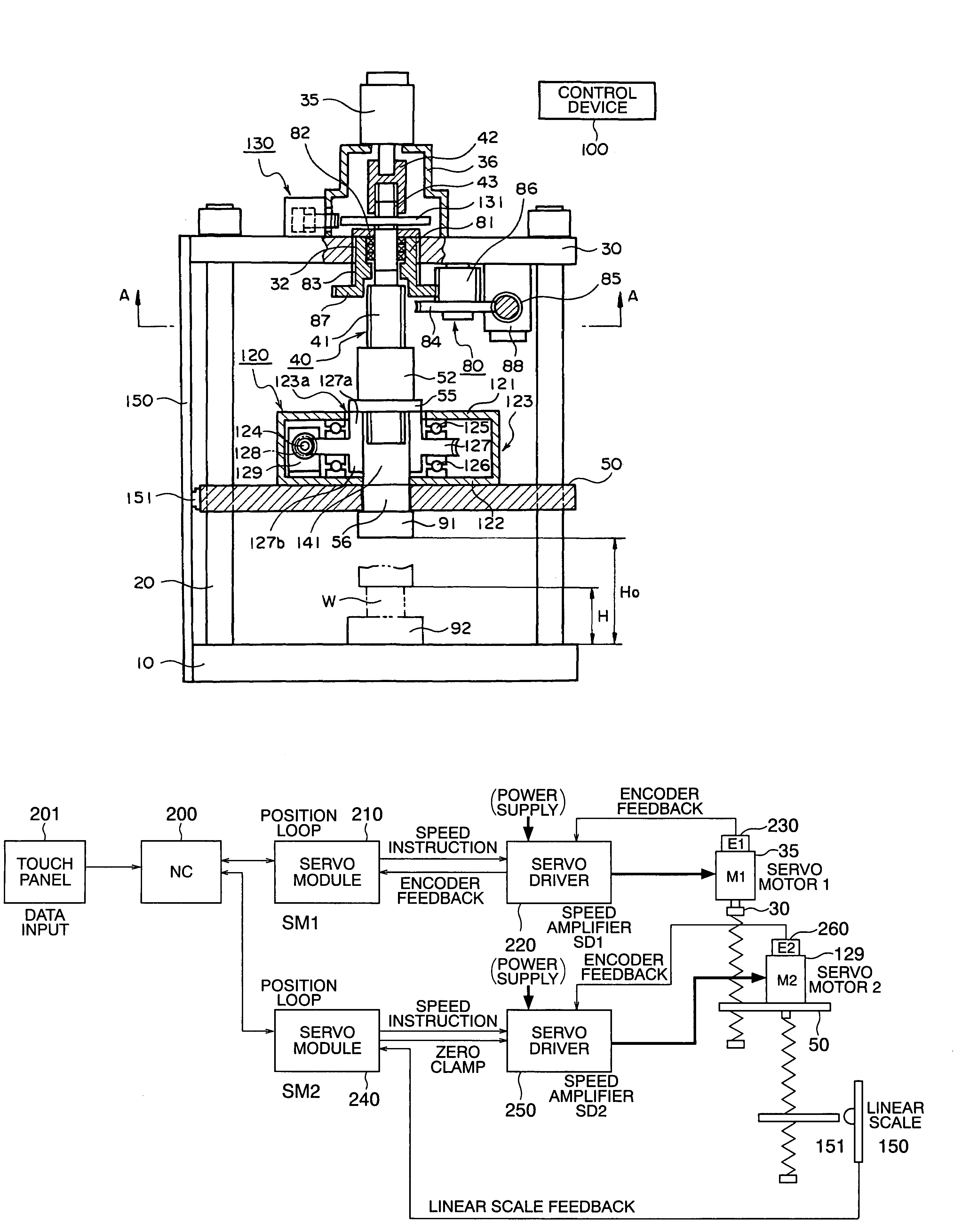
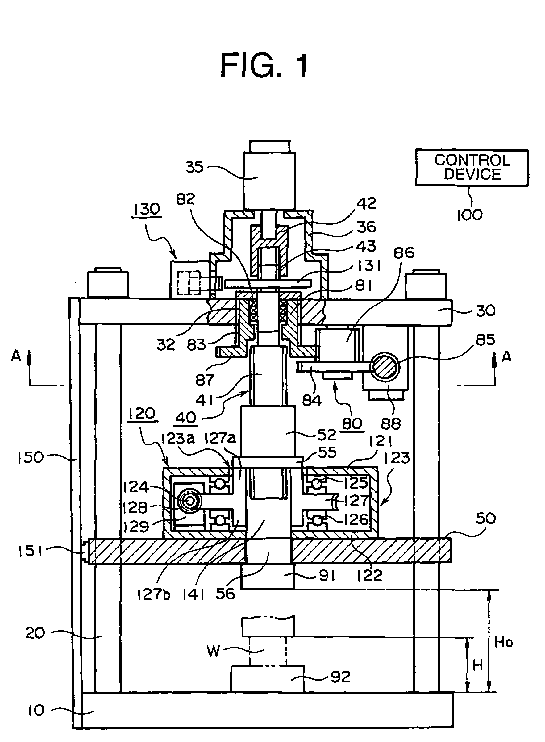
[0099]FIG. 1 is a front view of an embodiment in which a part of a main part of a pressing apparatus according to the invention is shown in section. FIG. 2 is a main part sectional view along an arrow A-A in FIG. 1. In these figures, components identical with those in FIGS. 34 and 36 are denoted by the identical reference numerals and signs.

[0100]The pressing apparatus includes a rectangular base 10, guide columns 20 erected at four corners of the base 10, and a support plate 30 supported by the guide columns 20 in parallel to the base 10. Further, a slider 50 (which also serves as a slide plate in this context) is provided between the base 10 and the support plate 30 to be guided by the guide columns 20 and move up and down freely along the guide columns 20.

[0101]A servomotor (a first motor) for fast feed 35 incorporating an encoder is attached to the support plate 30 via an attachment stand 36. A screw shaft 40 extending from a rotation shaft of the servomotor for fast feed 35 pie...


PUM

PropertyMeasurementUnit
diameteraaaaaaaaaa
diameteraaaaaaaaaa
movementaaaaaaaaaa

Abstract

A pressing apparatus using a motor, in which a fast feed drive lowers an upper die to a position immediately before pressing, and a motor for pressing performs a pressing operation. The fast feed drive and the motor for pressing operate cooperatively, and only one position detector, which detects a present position of a slider, is provided for a set of the fast feed drive and the motor for pressing.

Description

TECHNICAL FIELD[0001]The present invention relates to a pressing apparatus that is used for thin plate working and the like. In particular, the invention relates to a pressing apparatus that has a simple structure, makes it possible to carry out fixed-stroke press operation, which requires accurate position control, accurately and efficiently and also makes it possible to carry out cooperative operations of a servomotor for fast feed and a servomotor for pressing while using a signal from a position detector.BACKGROUND ART[0002]The fixed-stroke press operation by an electric press has been used conventionally and it is known that the fixed-stroke press operation is advantageous in preventing occurrence of noise.[0003]According to the electric press for performing the fixed-stroke press operation, it is possible to carry out the fixed-stroke press operation without causing noise. However, the conventional electric press has problems described below. A height dimension up to an pushin...

Claims


Application Information

Patent Timeline
Patent Type & Authority Patents(United States)
IPC IPC(8): B30B15/14B30B1/18
CPCB30B15/14B30B1/18B30B1/186
Inventor FUTAMURA, SHOJIMATSUMOTO, TAKEO
Owner HODEN SEIMITSU KAKO KENKYUSHO CO LTD
Why Eureka
Try Eureka