Pressure welding machine and pressure welding method

a welding machine and welding method technology, applied in the direction of soldering media, non-electric welding apparatus, soldering auxiliaries, etc., can solve the problems of large design effort, undesired deformations cannot be absorbed, and the accessibility of the workplace is limited, so as to achieve better pressure welding

Active Publication Date: 2010-08-19
KUKA SYSTEMS
View PDF8 Cites 20 Cited by
  • Summary
  • Abstract
  • Description
  • Claims
  • Application Information

AI Technical Summary

Benefits of technology

[0007]The pressure welding machine according to the invention has the advantage of requiring a substantially reduced design effort, and a larger working range and better accessibility of the workplace are also achieved at the same time. The forces occurring during upsetting are absorbed in a closed system of forces via the adjusting element, which relieves the load on the frame construction. At the same time, adjustment of the adjusting units in both directions with the feed drives along a preferably common and continuous guide plane can be achieved by means of the adjusting element. Moreover, this adjustment may be symmetrical. Special advantages are offered here by the adjusting element being designed as a continuous spindle with two threads directed in opposite directions, which is connected to the adjusting units via corresponding nut mounts. A self-locking motion thread, which can absorb and support the strong upsetting forces, is favorable here.
[0008]A preferably likewise displaceable central clamping device, which is equipped with two workpiece holders, which are connected to the respective adjusting units associated with them via carriage adjusters, are present for the central workpiece. As a result, the central clamping device and the adjusting units can be positioned simultaneously and synchronously. A spring-loaded connection between the carriage adjusters and the workpiece holders makes possible an evading motion of the workpiece holders to absorb the upsetting deformation of the central workpiece during the upsetting stroke.
[0009]The pressure welding machine according to the invention may have, moreover, a measuring means, which makes it possible to measure the true feeds and the pure shortenings of the workpiece during pressure welding without the elastic deformations of the central workpiece that occur during upsetting. It is possible as a result to also extrapolate the process parameters determined during a pressure welding process for certain workpieces and workpiece lengths to other workpieces of the same kind but with different lengths. This was hitherto impossible because the elastic deformation of the central workpiece, which likewise changed during a change of the workpiece lengths and thus affected the process parameters, was always contained in the path measured values. It is favorable for the measuring means being claimed to arrange a scale and a corresponding measuring head at the workpiece holder and at the associated welding head in such a way that they are movable in relation to one another, so that what is measured is precisely their motion. The elastic deformation of the central workpiece is eliminated via the elastically non-rigid mobility of the workpiece clamping device.

Problems solved by technology

This means a great design effort, and undesired deformations nevertheless cannot be absorbed.
On the other hand, the accessibility of the workplace is limited by the large frame construction.
The adjusting units are fixed here rigidly and unmovably to the machine bed.

Method used


Image

  • Pressure welding machine and pressure welding method
  • Pressure welding machine and pressure welding method
  • Pressure welding machine and pressure welding method

Examples


Embodiment Construction

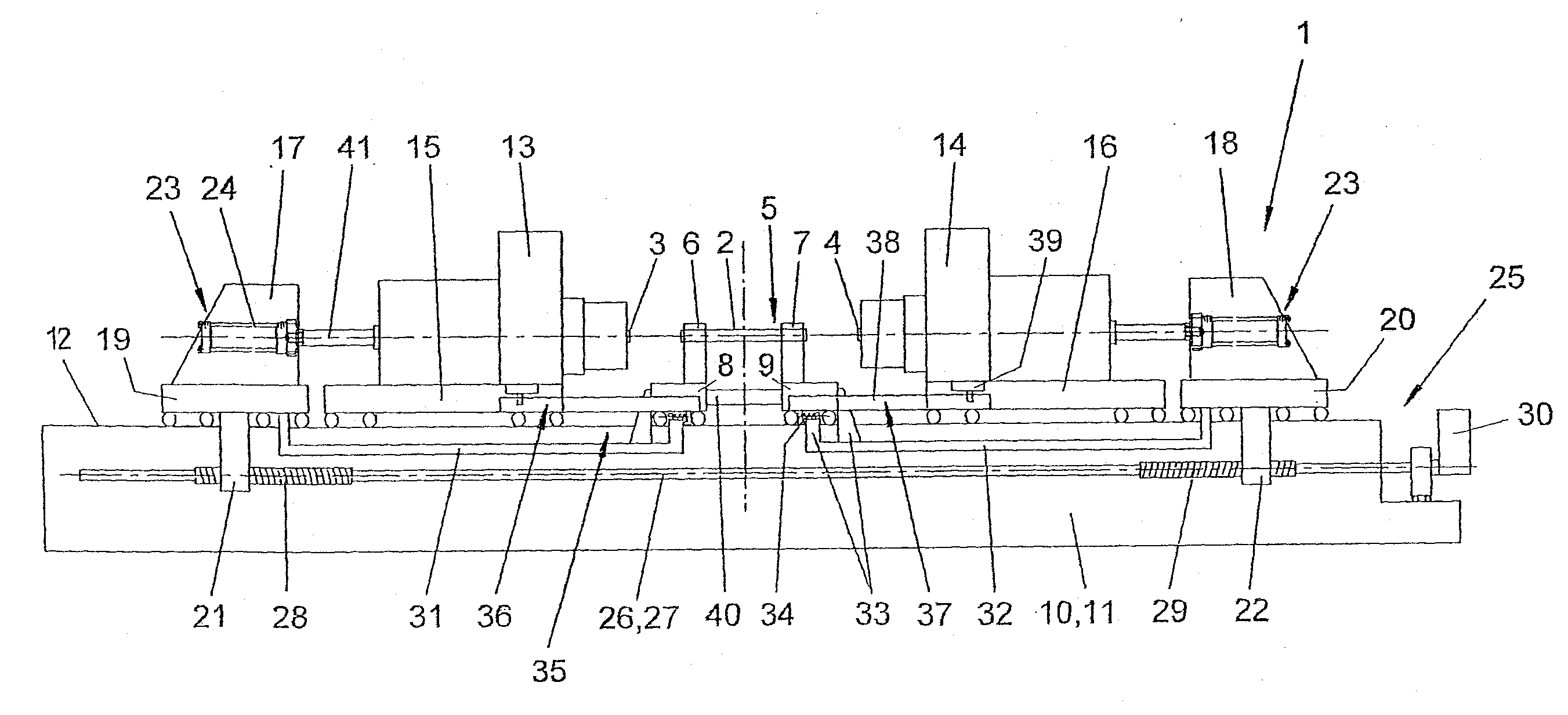
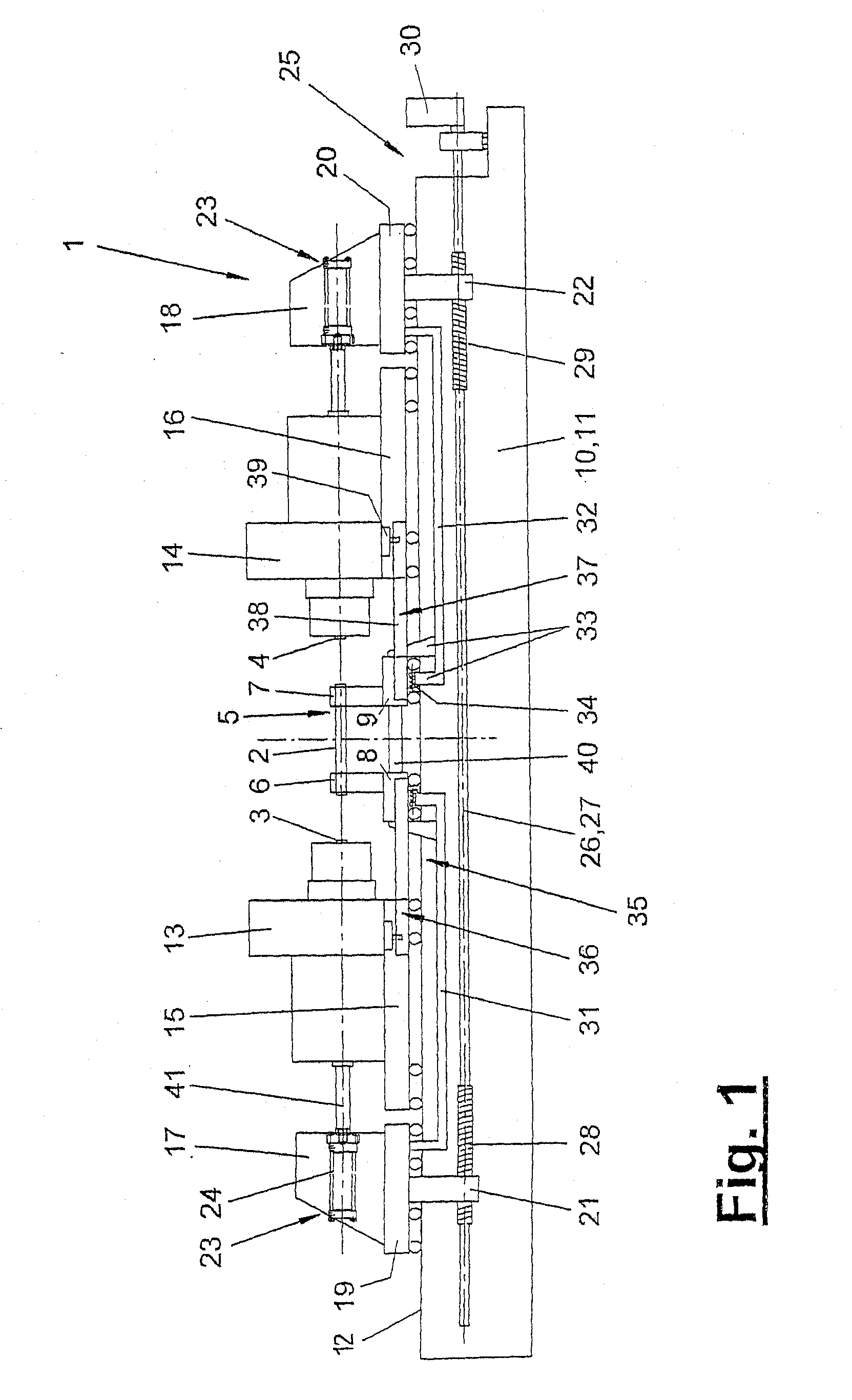
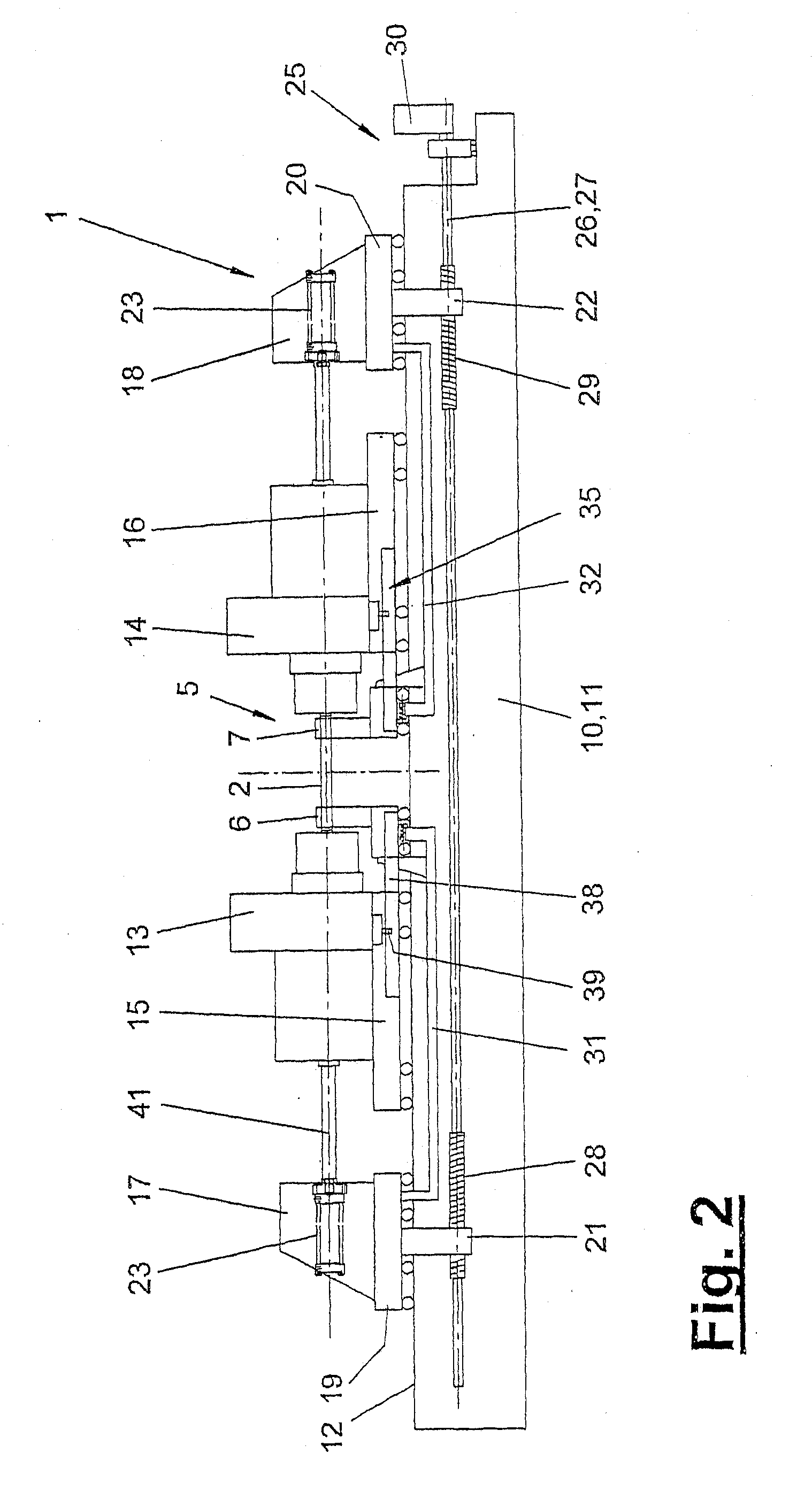
[0016]Referring to the drawings in particular, FIGS. 1 through 3 show schematic side views and different operating positions of a pressure welding machine (1). The pressure welding machine (1) is used to weld two, three or more workpieces (2, 3, 4), wherein one or more outer workpieces (3, 4) are welded to a central workpiece (2) at both ends. The pressure welding technique may be of any desired type. For example, it may be friction welding with direct motor drive or flywheel drive or welding with an arc moved magnetically or in another way, etc. The workpieces (2, 3, 4) are arranged along a preferably common feed axis or upsetting axis (41) and are moved toward one another and connected to one another at the end of the pressure welding operation by an upsetting stroke.

[0017]The pressure welding machine (1) is designed as a so-called double-head machine. It comprises a frame (10) with a central clamping device (5) for the central workpiece (2), two mobile welding heads (13, 14) adjo...


PUM

PropertyMeasurementUnit
forcesaaaaaaaaaa
elastic deformationaaaaaaaaaa
pressure welding forcesaaaaaaaaaa

Abstract

A pressure welding method is provided and a pressure welding machine (1) is provided with a frame (10), two welding heads (13, 14), mobile along a feed axis (41), and two adjusting units (17, 18). The adjusting units (17, 18) include feed drives (23) for the welding heads (13, 14). The two adjusting units (17, 18) are mounted so as to be axially movable (41) on the frame (10) and are interlinked with an adjusting drive (25) by means of a common adjusting element (26) and supported in a closed system of forces while receiving the pressure welding forces, thereby relieving the frame (10). The common adjusting element (26) is configured as a continuous spindle (27) having two self-locking threads (28, 29) that run in opposite directions.

Description

CROSS REFERENCE TO RELATED APPLICATIONS[0001]This application is a continuation of U.S. application Ser. No. 10 / 599,390 filed Sep. 26, 2006, which is a United States National Phase application of International Application PCT / EP2005 / 006766 and claims the benefit of priority under 35 U.S.C. §119 of German Patent Application DE 20 2004 101 386.9 filed Jul. 1, 2004, the entire contents of which are incorporated herein by reference.FIELD OF THE INVENTION[0002]The present invention pertains to a pressure welding machine and a pressure welding method.BACKGROUND OF THE INVENTION[0003]Such a pressure welding machine is known in the form of a double-head friction welding machine from EP 0 246 239 B1. It comprises a frame with a machine bed, at which two friction welding heads are mounted in such a way that they are movable in opposite directions along a common feed axis. They are moved by two adjusting units with feed drives along the feed axis. The adjusting units are mounted adjustably at ...

Claims


Application Information

Patent Timeline
Patent Type & Authority Applications(United States)
IPC IPC(8): B23K31/02B23K9/00B23K20/02B23K20/12B23K37/02
CPCB23K20/121B23K20/12
Inventor RUDOLPH, FRANKHAUCK, THOMASMEYER, HARALDSCHNEIDER, KLAUSMENZINGER, MANFREDFISCHER, OTMAR
Owner KUKA SYSTEMS
Why Eureka
Try Eureka