Controlled waveform welding wire feeder system and method

a feeder system and waveform welding technology, applied in the field of controlled waveform welding wire feeder system and method, can solve problems such as affecting the timing or amplitude of pulses

Active Publication Date: 2013-12-12
ILLINOIS TOOL WORKS INC
View PDF5 Cites 18 Cited by
  • Summary
  • Abstract
  • Description
  • Claims
  • Application Information

AI Technical Summary

Benefits of technology

[0006]In one embodiment, a welding wire feeder includes a welding wire feed drive configured to drive welding wire towards a welding application and wire feed control circuitry coupled to the welding wire feed drive. The wire feed control circuitry is also configured to control the drive of welding wire towards the welding application. The welding wire feeder also includes power conversion circuitry and welding process control circuitry coupled to the power conversion circuitry. The power conversio

Problems solved by technology

Unfortunately, lengthy power cables between a welding power source and a welding applic

Method used


Image

  • Controlled waveform welding wire feeder system and method
  • Controlled waveform welding wire feeder system and method
  • Controlled waveform welding wire feeder system and method

Examples


Embodiment Construction

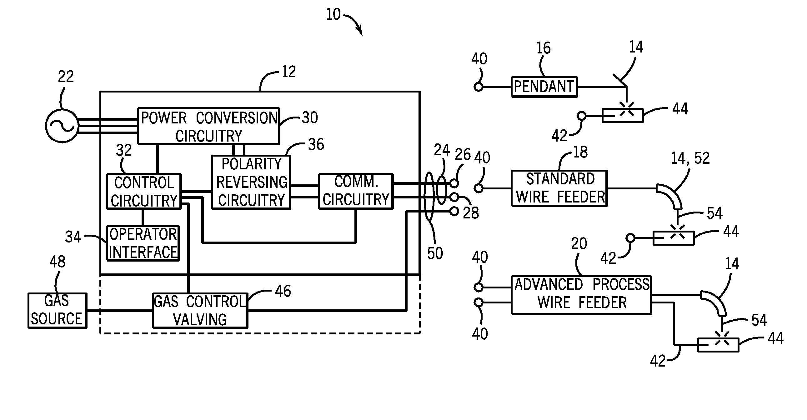
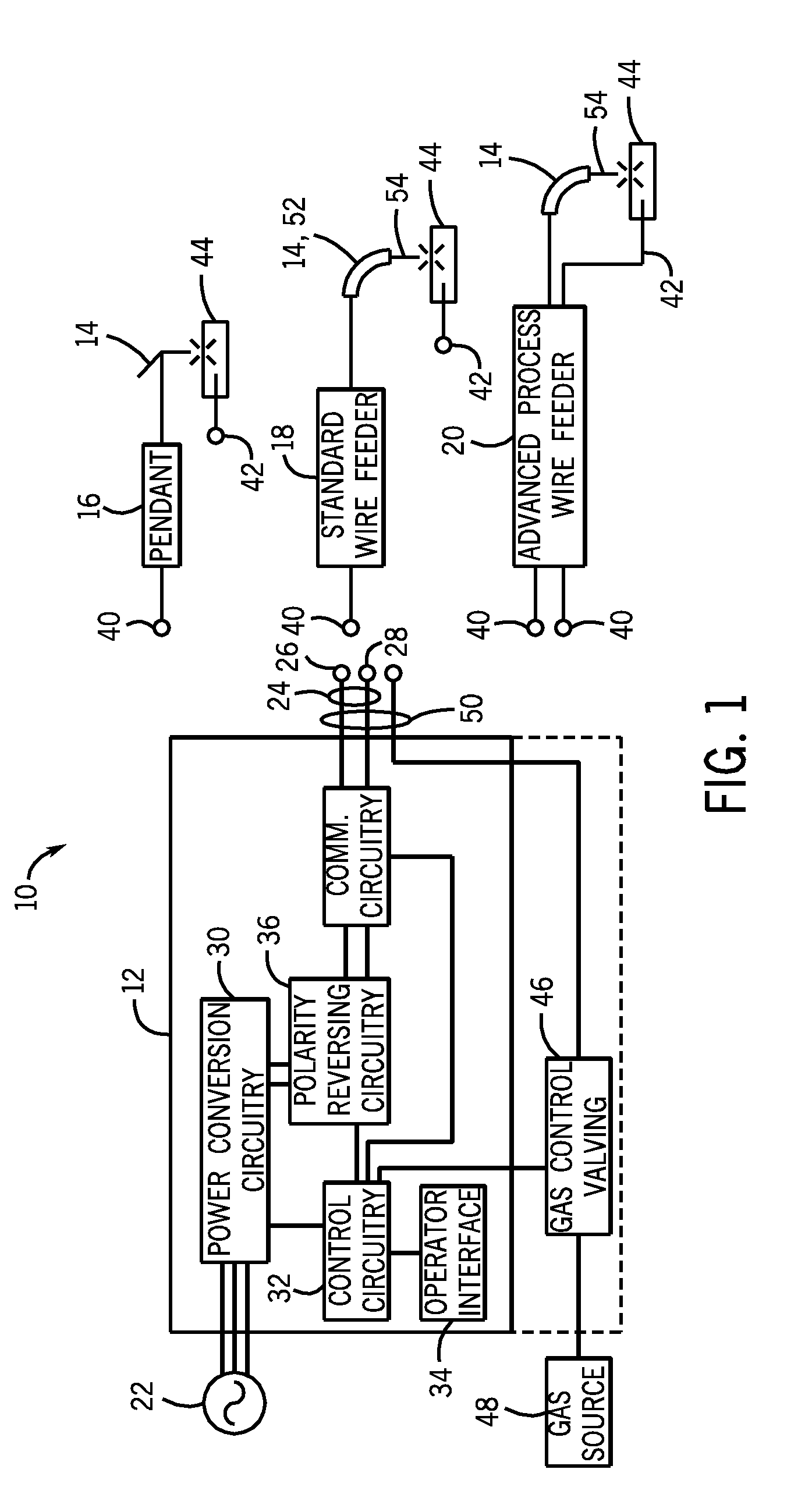
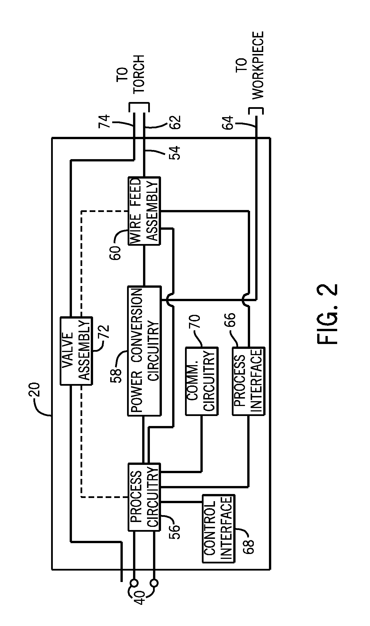
[0026]FIG. 1 is a block diagram of an embodiment of a welding system 10 which powers a welding application. As illustrated, the welding system 10 includes a welding power source 12 and a coupled welding torch 14. The welding power source 12 supplies input power to the welding torch 14. The welding torch 14 may be a torch configured for stick welding, tungsten inert gas (TIG) welding, or gas metal arc welding (GMAW), based on the desired welding application. In some embodiments, the welding power source 12 supplies input power to a pendant 16 coupled to a torch 14 configured for stick welding or TIG welding. The operator supplies the filler metal, if any, for stick or TIG welding. The pendant 16 may be configured to control the power source 12 and / or notify the operator of welding parameters. In other embodiments, the welding power source 12 supplies input power to a standard wire feeder 18. The standard wire feeder 18 supplies the input power and filler metal to a welding torch 14 c...


PUM

PropertyMeasurementUnit
Electric potential / voltageaaaaaaaaaa
Poweraaaaaaaaaa
Electrical inductanceaaaaaaaaaa

Abstract

A welding wire feeder includes a welding wire feed drive configured to drive welding wire towards a welding application and wire feed control circuitry coupled to the welding wire feed drive. The wire feed control circuitry is also configured to control the drive of welding wire towards the welding application. The welding wire feeder also includes power conversion circuitry and welding process control circuitry coupled to the power conversion circuitry. The power conversion circuitry is configured to receive input power from a welding power source and to convert the input power to controlled waveform welding output. The welding process control circuitry is configured to provide control signals for conversion of the input power to the controlled waveform welding output. The welding wire feeder also includes a process operator interface coupled to the welding process control circuitry and configured to permit operator selection of a controlled waveform welding process.

Description

CROSS-REFERENCE TO RELATED APPLICATION[0001]This application claims priority from and the benefit of U.S. Provisional Application Ser. No. 61 / 657,467, entitled “CONTROLLED WAVEFORM WELDING WIRE FEEDER SYSTEM AND METHOD,” filed Jun. 8, 2012, which is hereby incorporated by reference in its entirety for all purposes.BACKGROUND[0002]The invention relates generally to welding systems, and, more particularly, to controlled waveform welding wire feeder systems and methods.[0003]Welding systems support a variety of processes, such as metal inert gas (MIG) welding, tungsten inert gas (TIG) welding, stick welding, and so forth, which may operate in different modes, such as constant current or constant voltage. Certain welding applications, such as boiler servicing and repair, shipyard work, construction, and so forth, may position a welding location or workpiece large distances from a welding power source.[0004]Power cables supply output power to a welding application from the welding power ...

Claims


Application Information

Patent Timeline
IPC IPC(8): B23K9/12
CPCB23K9/124B23K9/09B23K9/1006
Inventor ROTH, MICHAEL WILLIAMRYAN, JOSEPH ROBERTSALSICH, ANTHONY VAN BERGENDANTINNE, MARKUS MICHAELVEIK, BRIAN JAMES
Owner ILLINOIS TOOL WORKS INC
Why Eureka
Try Eureka