
Apparatus for estimating arrival-angle and apparatus for beam-forming

a beam-forming apparatus and arrival-angle technology, applied in direction finders using radio waves, instruments, reradiation, etc., can solve the problem that signals received by a plurality of receiving channels may have different phase values, and achieve accurate estimation of arrival-angle, improve beam-forming accuracy of reception signals, and improve measurement accuracy of arrival-angles

Active Publication Date: 2019-08-20
HL KLEMOVE CORP +1
View PDF2 Cites 2 Cited by
  • Summary
  • Abstract
  • Description
  • Claims
  • Application Information

AI Technical Summary

Benefits of technology

[0016]The object of the present embodiment is to provide an apparatus that is able to improve the receiving performance of the radar.
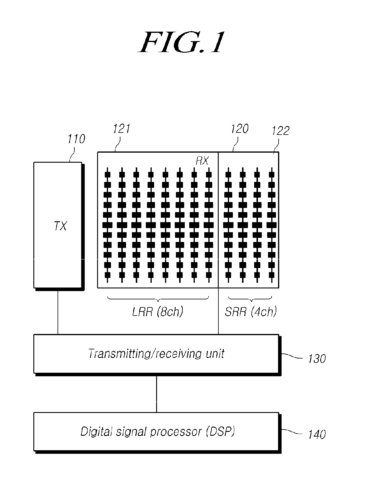
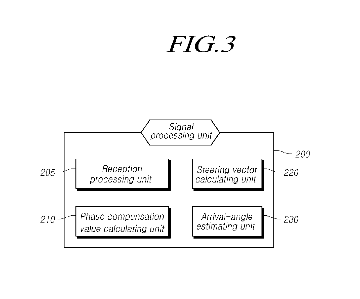
[0018]Another object of the present invention is to provide an apparatus for estimating an arrival-angle or an apparatus for performing the beam-forming, which may: predetermine a reference value that is obtained by calculating the degree of distortion of the magnitude and phase of a signal for each measurement angle; calculate a phase compensation value by using the reference value; and accurately estimate an arrival-angle of a reception signal by using the phase compensation value, or perform the beam-forming of a reception signal by using the reference value.
[0019]Another object of the present invention is to provide an apparatus that performs the signal processing by using a reference value that is obtained by calculating the degree of distortion of the magnitude and phase for each measurement angle in order to: thereby reduce an estimation error of the arrival-angle according to a mismatch between the magnitude and the phase for each receiving channel, a positional error of a sensor, a signal directing error, and a mutual coupling problem; and thereby reduce a beam-forming error.
[0025]The measuring apparatus, such as radar, according to the embodiment of the present invention, may set a reference value for each measurement angle, and may estimate an arrival-angle of the reception signal or may perform the beam-forming of the reception signal by using the reference value in order to thereby improve the measurement accuracy of the arrival-angle and the directivity of beam-forming.
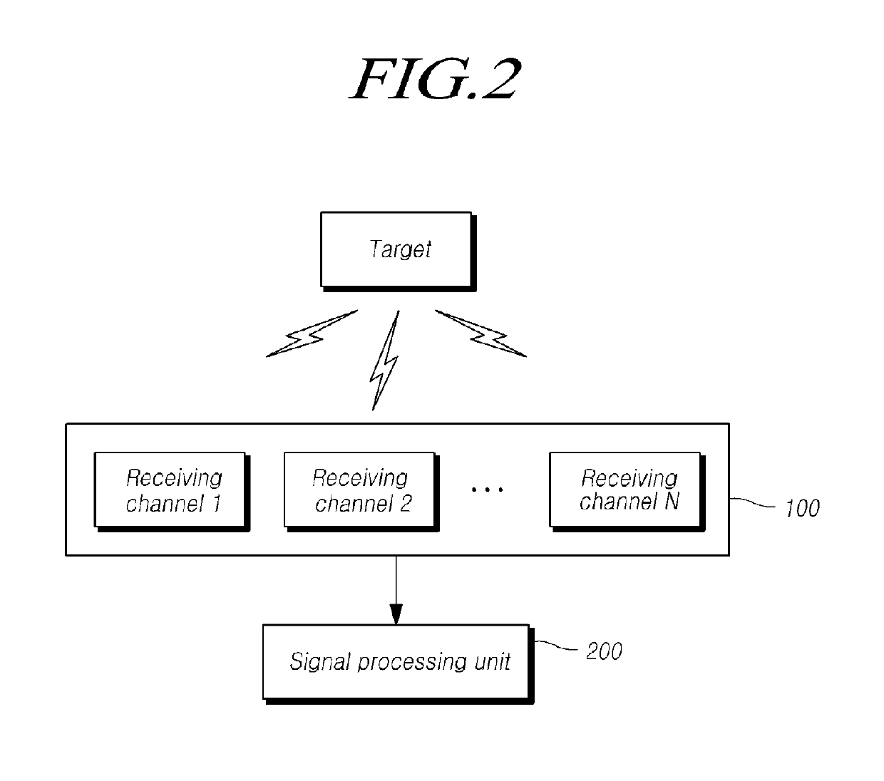
[0026]More specifically, the apparatus may predetermine a reference value, which is obtained by calculating the degree of distortion of the magnitude and phase of a signal for each measurement angle, and may use a phase compensation value that is calculated according to the comparison with the reference value in order to thereby accurately estimate the arrival-angle of the reception signal and in order to thereby improve the beam-forming accuracy of the reception signal.
[0027]As a result, it is possible to reduce an estimation error of the arrival-angle according to a positional error of the receiving antenna, a signal directing error, and a mutual coupling problem, and to reduce a beam-forming error by correcting both an error for each measurement angle and an error for each receiving channel.

Problems solved by technology

Meanwhile, in the typical radar devices, the reception signals that are received by a plurality of receiving channels may have different phase values due to hardware problems.

Method used


Image

  • Apparatus for estimating arrival-angle and apparatus for beam-forming
  • Apparatus for estimating arrival-angle and apparatus for beam-forming
  • Apparatus for estimating arrival-angle and apparatus for beam-forming

Examples


Embodiment Construction

[0037]Hereinafter, some embodiments of the present invention will be described in detail with reference to the accompanying illustrative drawings. In designating elements of the drawings by reference numerals, the same elements will be designated by the same reference numerals although they are shown in different drawings. Further, in the following description of the present invention, a detailed description of known functions and configurations incorporated herein will be omitted when it may make the subject matter of the present invention rather unclear.

[0038]In addition, terms, such as first, second, A, B, (a), (b) or the like may be used herein when describing components of the present invention. Each of these terminologies is not used to define an essence, order or sequence of a corresponding component but used merely to distinguish the corresponding component from other component(s). In the case that it is described that a certain structural element “is connected to”, “is coup...


PUM


Abstract

The present invention relates to an apparatus for estimating an arrival-angle of a reception signal and a beam-forming apparatus in a radio wave receiver, such as radar. More specifically, the present invention relates to an apparatus for accurately estimating an arrival-angle of a reception signal, or an apparatus for performing the beam-forming of a reception signal by using a multi-reception array antenna, by using a reference value that is obtained by calculating the degree of distortion of the magnitude and phase of a signal for each reception angle.

Description

CROSS REFERENCE TO RELATED APPLICATION[0001]This application claims priority from Korean Patent Application No. 10-2015-0147490, filed on Oct. 22, 2015, which is hereby incorporated by reference for all purposes as if fully set forth herein.BACKGROUND OF THE INVENTION[0002]1. Field of the Invention[0003]The present invention relates to an apparatus for estimating an arrival-angle of a reception signal and a beam-forming apparatus in a radio wave receiver, such as radar. More particularly, the present invention relates to an apparatus for accurately estimating an arrival-angle of a reception signal, or an apparatus for performing the beam-forming of a reception signal by using a multi-reception array antenna, by using a reference value that is obtained by calculating the degree of distortion of the magnitude and phase of a signal for each reception angle.[0004]2. Description of the Prior Art[0005]Radar devices that are mounted on vehicles require a high-quality angular resolution. Fo...

Claims


Application Information

Patent Timeline
Patent Type & Authority Patents(United States)
IPC IPC(8): H04B7/06G01S3/72H04L5/00G01S7/40G01S13/93G01S13/34H04B7/08G01S13/931
CPCH04B7/0617G01S3/72G01S7/4021G01S13/931H04L5/0048G01S13/34H04B7/086G01S3/023G01S3/10Y02A90/10
Inventor LEE, JAEEUNLIM, HAESUENGJEONG, SEONG HEESHIN, HYUN-CHOOL
Owner HL KLEMOVE CORP
Learn More