Multi-carrier transmission apparatus, multi-carrier reception apparatus, and multi-carrier radio communication method

a multi-carrier transmission and multi-carrier technology, applied in the field of transmission/reception equipment, can solve the problems of poor efficiency, deterioration of transmission characteristics, and increase of influence of delay signals caused by multi-paths, so as to improve information transmission efficiency and reception performan

Active Publication Date: 2007-04-03
INTERDIGITAL PATENT HLDG INC
View PDF10 Cites 87 Cited by
  • Summary
  • Abstract
  • Description
  • Claims
  • Application Information

AI Technical Summary

Benefits of technology

[0016]It is an object of the present invention to provide a multicarrier transmission apparatus, multicarrier reception apparatus and multicarrier radio communication method based on a subcarrier transmission ON / OFF control system capable of improving the information transmission efficiency and reception performance while maintaining the number of transmission bits in an MC-CDMA system.

Problems solved by technology

However, when high-speed transmission is carried out in mobile communications, influences of delay signals caused by multipaths will grow to such an extent that they are no longer negligible and the transmission characteristic will deteriorate due to frequency selective fading.
However, the above-described conventional system 1 and conventional system 2 have problems as follows.
First, the conventional system 1 gives greater energy to subcarriers whose power decreases in a propagation path during transmission and gives smaller energy to subcarriers whose power increases in a propagation path during transmission (see FIG. 1A through FIG. 1C), which results in poor efficiency and puts a certain limit on improvement of the reception performance.
Moreover, since the transmit power is relatively large, the signal may cause interference with another cell.
To improve this, the conventional system 2 reduces the number of transmission bits by puncturing, but puncturing increases a coding rate and thereby reduces the error correcting performance.
Furthermore, the conventional system 2 turns OFF transmission by subcarriers of low reception quality, which reduces total transmit power and reduces the information transmission efficiency.
That is, according to the conventional system 2, subcarriers not to be involved in transmission are selected from among all subcarriers, and therefore if transmission of all spreading chips of a certain symbol in the MC-CDMA system is turned OFF, the symbol will no longer be transmitted completely, and as a result the performance deteriorates.
Moreover, if transmission OFF control is simply performed in the MC-CDMA system, the orthogonality of a transmission signal with multiplexed spreading codes will be completely destroyed and a signal being sent using a different spreading code will have completely the same signal waveform, preventing the receiving side from separating those signals.

Method used


Image

  • Multi-carrier transmission apparatus, multi-carrier reception apparatus, and multi-carrier radio communication method
  • Multi-carrier transmission apparatus, multi-carrier reception apparatus, and multi-carrier radio communication method
  • Multi-carrier transmission apparatus, multi-carrier reception apparatus, and multi-carrier radio communication method

Examples


embodiment 1

(Embodiment 1)

[0053]FIG. 3 is a block diagram showing configurations of a multicarrier transmission apparatus and a multicarrier reception apparatus according to Embodiment 1 of the present invention.

[0054]The multicarrier transmission apparatus (hereinafter simply referred to as “transmitter”) 100 shown in FIG. 3 is provided with a spreading section 102, a serial / parallel conversion (S / P) section 104, a transmission control section 106, a power control section 108, an inverse fast Fourier transform (IFFT) section 110, a parallel / serial conversion (P / S) section 112, a guard interval (GI) insertion section 114, a transmission RF section 116, a transmission / reception duplex antenna 118, a reception RF section 120, an ON / OFF information extraction section 122 and a carrier selection section 124. The transmitter 100 is mounted, for example, on a base station in a mobile communication system.

[0055]On the other hand, the multicarrier reception apparatus (hereinafter simply referred to as ...

embodiment 2

(Embodiment 2)

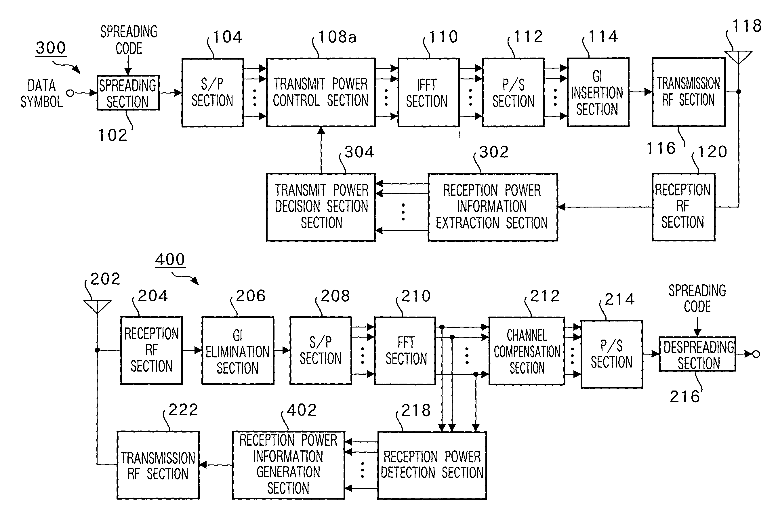
[0093]FIG. 7 is a block diagram showing configurations of a multicarrier transmission apparatus and a multicarrier reception apparatus according to Embodiment 2 of the present invention. The multicarrier transmission apparatus (transmitter) 300 and multicarrier reception apparatus (receiver) 400 have the same basic configurations as those of the multicarrier transmission apparatus (transmitter) 100 and multicarrier reception apparatus (receiver) 200 shown in FIG. 3, and therefore the same components are assigned the same reference numerals and explanations thereof will be omitted.

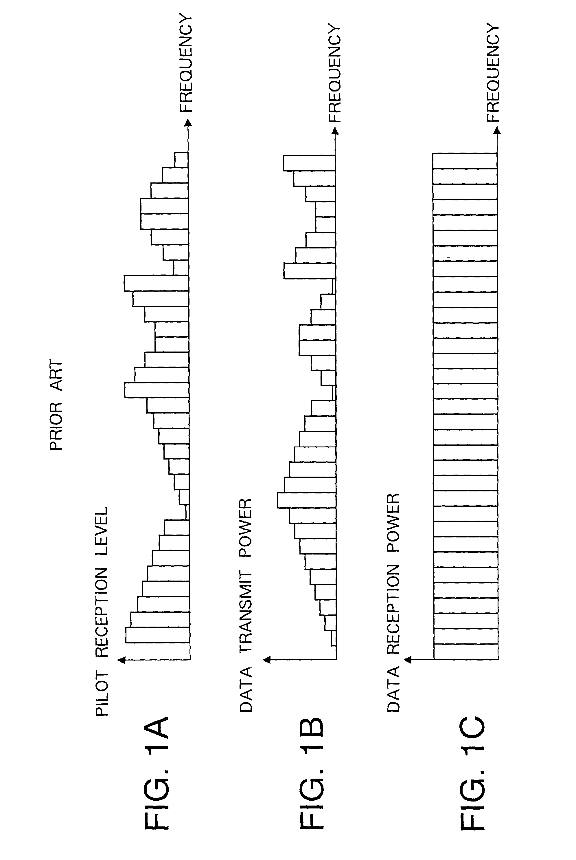
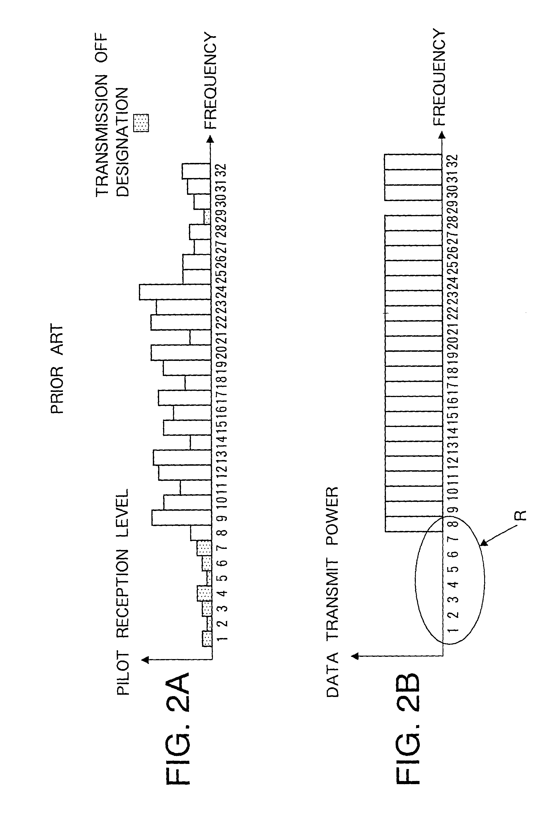
[0094]A feature of this embodiment consists in subcarrier transmit power control opposite the conventional system 1 (referred to “subcarrier reverse transmit power control” here), or more particularly, for example, this embodiment based on an MC-CDMA system carries out transmission according to a reception level of each subcarrier at the receiver 400 with subcarriers with higher reception leve...


PUM


Abstract

A subcarrier transmission ON/OFF control system based on an MC-CDMA system capable of improving information transmission efficiency and reception performance while keeping the number of transmission bits constant. Furthermore, a subcarrier transmit power control system based on an MC-CDMA system or OFDM system capable of improving information transmission efficiency and reception performance. The former system based on the MC-CDMA system does not carry out transmission through subcarriers of low reception quality, with no transmit power assigned (transmission OFF), assigns the corresponding transmit power to subcarriers with transmit power assigned (transmission ON) and carries out transmission (subcarrier transmission ON/OFF control) The latter system based on the MC-CDMA system or OFDM system carries out transmission according to a reception level of each subcarrier on the receiving side, with greater transmit power assigned to subcarriers with higher reception levels and smaller transmit power assigned to subcarriers with lower reception levels (subcarrier reverse transmit power control).

Description

TECHNICAL FIELD[0001]The present invention relates to a transmission / reception apparatus, and more particularly, to a multicarrier transmission apparatus, multicarrier reception apparatus and multicarrier radio communication method.BACKGROUND ART[0002]In a radio communication, a mobile communication in particular, not only voice but also various types of information such as images and data are becoming objects of transmission in recent years. With anticipation of increasing demands for transmission of a variety of contents in the future, it is estimated that the need for more reliable and faster transmission will be further increased. However, when high-speed transmission is carried out in mobile communications, influences of delay signals caused by multipaths will grow to such an extent that they are no longer negligible and the transmission characteristic will deteriorate due to frequency selective fading.[0003]As one of technologies for coping with frequency selective fading, a m...

Claims


Application Information

Patent Timeline
Patent Type & Authority Patents(United States)
IPC IPC(8): H04K1/10H04L27/28H04J11/00H04B1/707H04B7/005H04B7/26H04J13/00H04L27/26H04W52/04H04W52/34
CPCH04B1/692H04W52/346H04L1/0025H04L1/0026H04L1/0032H04L1/0034H04L27/2608H04W52/42Y02B60/50
Inventor MIYOSHI, KENICHI
Owner INTERDIGITAL PATENT HLDG INC
Why Eureka
Try Eureka