Coupled structure and electronic device

a technology of electronic devices and coupling structures, applied in emergency protective devices, instruments, portable computers, etc., can solve problems such as disengagement of hooks, deterioration of appearance, and displacement of keyboard units during coupling, so as to prevent lowering or loss of biasing force, facilitate and reliably coupling, and improve appearance of electronic devices

Active Publication Date: 2019-10-01
LENOVO (SINGAPORE) PTE LTD
View PDF21 Cites 1 Cited by
  • Summary
  • Abstract
  • Description
  • Claims
  • Application Information

AI Technical Summary

Benefits of technology

[0012]The locking part may extend in the one direction and have an upper face continuous to the locking face, and the upper face of the locking part may have a length in the one direction that is longer than an engagement length of the hook with the engagement hole. This prevents the elastic part from being mounted on the upper face of the locking part before the engagement by the hook mechanism and getting caught at the end toward the other direction during the coupling of the first member with the second member, so that the first member cannot slide in the engagement direction.
[0013]An electronic device according to the second aspect of the present invention includes the above-stated coupled structure. The first member is a keyboard unit, and the second member is a chassis having an upper face on which the keyboard unit is mounted. With this configuration, the keyboard unit can be easily and reliably coupled with the upper face of the chassis of the electronic device, and their coupling state can be kept.
[0014]Preferably the one direction is a direction toward an end of the keyboard unit closer to a user of the electronic device. A biasing force from the elastic part then can reduce the gap between the end of the keyboard unit closer to the user and the chassis, and so the appearance of the electronic device can be improve

Problems solved by technology

Such a structure as in Patent Document 1, for coupling a keyboard unit with a main body chassis via a hook mechanism, however, may cause displacement of the keyboard unit during the manufacturing or operation of the electronic device.
This may lead to disengagement of the hook, and further may lead to deteriorati

Method used


Image

  • Coupled structure and electronic device
  • Coupled structure and electronic device
  • Coupled structure and electronic device

Examples


Embodiment Construction

[0032]Referring to the attached drawings, the following describes a coupled structure according to the present invention in details, by way of a preferable embodiment of an electronic device including such a coupled structure.

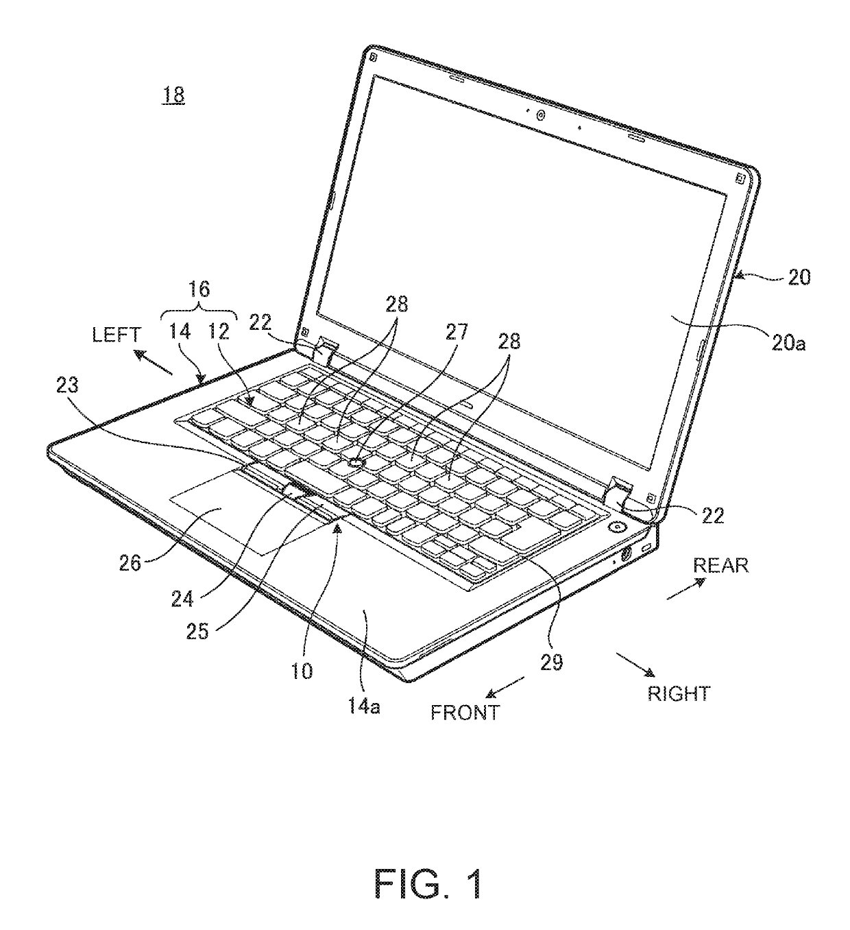
[0033]FIG. 1 is a perspective view of an electronic device 18 including a coupled structure 16 according to one embodiment of the present invention. This coupled structure includes a keyboard unit 12 coupled with a main body chassis 14 via a coupling structure 10. In the following description of the coupled structure 16, referring to the keyboard unit mounted on the electronic device 18 for use shown in FIG. 1, the forward and the back are called front and rear, respectively, the thickness direction is called vertically (up and down), and the width direction is called left and right.

[0034]As shown in FIG. 1, the electronic device 18 is a laptop PC, including the main body chassis 14 having the keyboard unit 12 and a display chassis 20 having a display unit 20a,...


PUM


Abstract

A coupled structure capable of keeping the coupled state between coupled members without degrading the appearance, and an electronic device including such a coupled structure are disclosed. A coupled structure includes a keyboard unit coupled with a main body chassis. The coupled structure includes a hook mechanism which engages the keyboard unit with the main body chassis when the keyboard unit moves in one direction relative to the main body chassis, a locking part formed at the main body chassis, and an elastic part formed at the keyboard unit, and the elastic part biases the keyboard unit engaged with main body chassis in the one direction relative to the main body chassis when the locking part locks the elastic part.

Description

TECHNICAL FIELD[0001]The present invention relates to a coupled structure including two coupled members and an electronic device including such a coupled structure.BACKGROUND[0002]An electronic device, such as a laptop personal computer (laptop PC), typically includes a keyboard unit attached to an upper face of the chassis (hereinafter called a main body chassis) of its main body. Patent Document 1, for example, discloses the structure having a recess at the upper face of the main body chassis so as to store a keyboard unit in this recess. This keyboard unit has a hook protruding from its lower face, and the keyboard unit is fixed to the main body chassis by engaging the hook with an engagement hole at the bottom face of the recess.[0003][Patent Document 1] Japanese Patent Application Laid-Open No. 11-265251SUMMARY OF THE INVENTION[0004]Such a structure as in Patent Document 1, for coupling a keyboard unit with a main body chassis via a hook mechanism, however, may cause displaceme...

Claims


Application Information

Patent Timeline
IPC IPC(8): G06F1/16G06F3/02
CPCG06F3/0213G06F1/1662G06F3/0221G06F1/1616G06F3/0202H01H13/86H01H2223/01H01H2223/026H01H2223/024
Inventor KITAMURA, MASAHIROHORIUCHI, MITSUODOUZONO, SATOSHI
Owner LENOVO (SINGAPORE) PTE LTD
Why Eureka
Try Eureka