
Touch panel structure

a touch panel and metal mesh technology, applied in the field of touch panel structure, can solve the problems of affecting user experience, increasing the visibility of the sensing electrode, and the conventional design of the metal mesh cannot meet the above-mentioned needs

Active Publication Date: 2019-10-01
INTERFACE TECH CHENGDU CO LTD +2
View PDF2 Cites 0 Cited by
  • Summary
  • Abstract
  • Description
  • Claims
  • Application Information

AI Technical Summary

Benefits of technology

[0049]In summary, the present disclosure provides a touch panel which can reduce the visible risk of the metal mesh and fulfill the requirement of lower line impedance in the future. The touch panel provided in the present disclosure may be used for any stylus, such as active stylus, passive stylus or mixed stylus. The touch sensing line has a better effect and lower resistance, improving the rate of the touch response because of the lower resistance of the metal mesh, and making the structure of the touch display device thinner, simplifying the process, reducing costs and increasing the yield. Different needs of ultra-narrow borders, borderless, flexible panel can be fulfilled due to the characteristics of the metal mesh.

Problems solved by technology

At present, the conventional design of the metal mesh cannot meet the above-mentioned needs.
However, increasing sensing pattern channel would make the metal mesh be observed by users easily, which increases the visibility of the sensing electrodes and affects the user experience.

Method used


Image

  • Touch panel structure
  • Touch panel structure
  • Touch panel structure

Examples


Embodiment Construction

[0023]Reference will now be made in detail to the present embodiments of the disclosure, examples of which are illustrated in the accompanying drawings. Wherever possible, the same reference numbers are used in the drawings and the description to refer to the same or like parts.

[0024]The following disclosure provides many different embodiments, or examples, for implementing different features of the provided subject matter. Specific examples of components and arrangements are described below to simplify the present disclosure. These are, of course, merely examples and are not intended to limit. For example, the formation of a first feature over a second feature in the description that follows may include embodiments in which the first and second features are formed in direct contact, and may also include embodiments in which additional features are disposed between the first and second features, such that the first and second features are not in direct contact. In addition, the pres...


PUM

PropertyMeasurementUnit
widthaaaaaaaaaa
widthaaaaaaaaaa
widthaaaaaaaaaa

Abstract

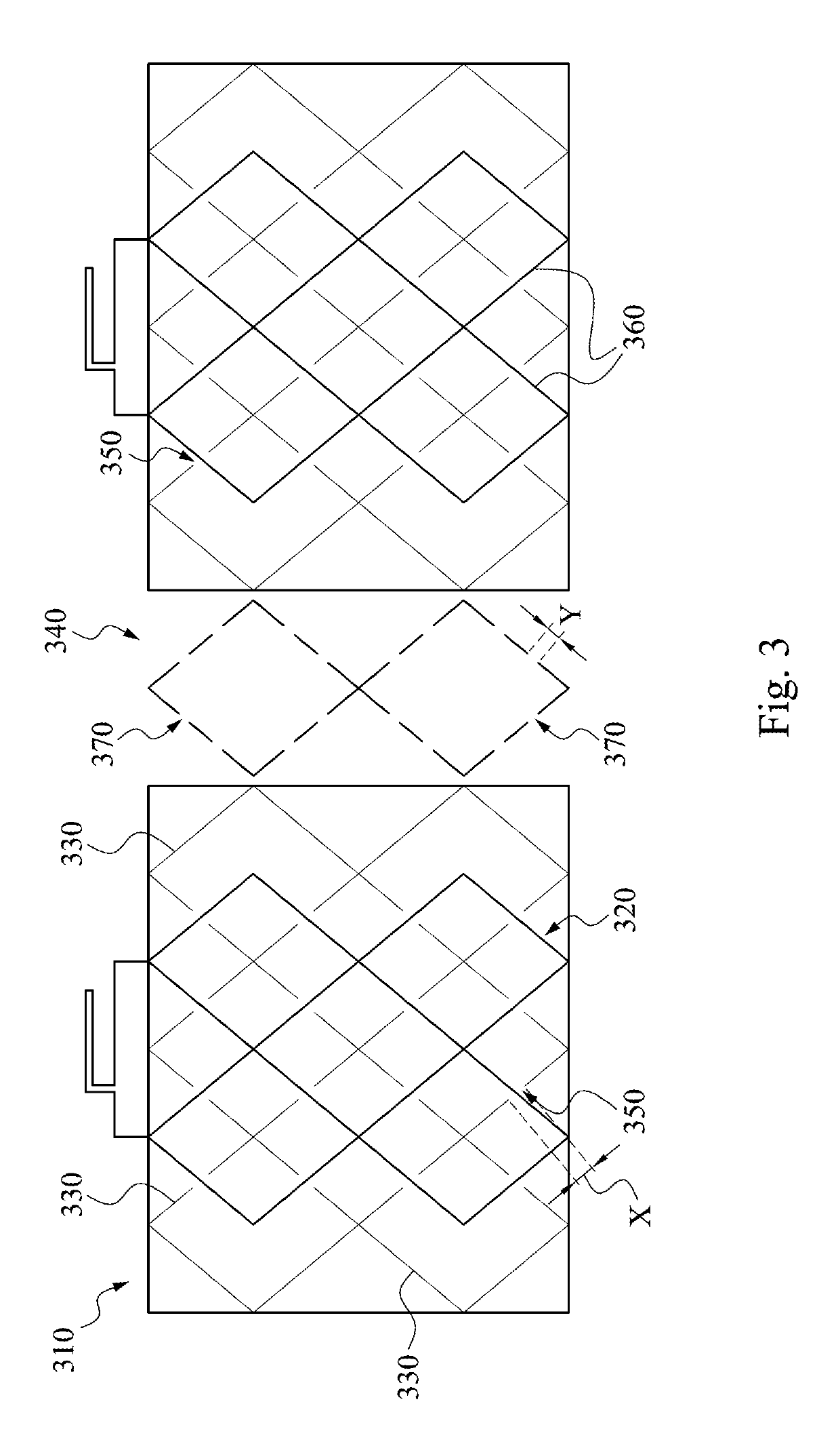
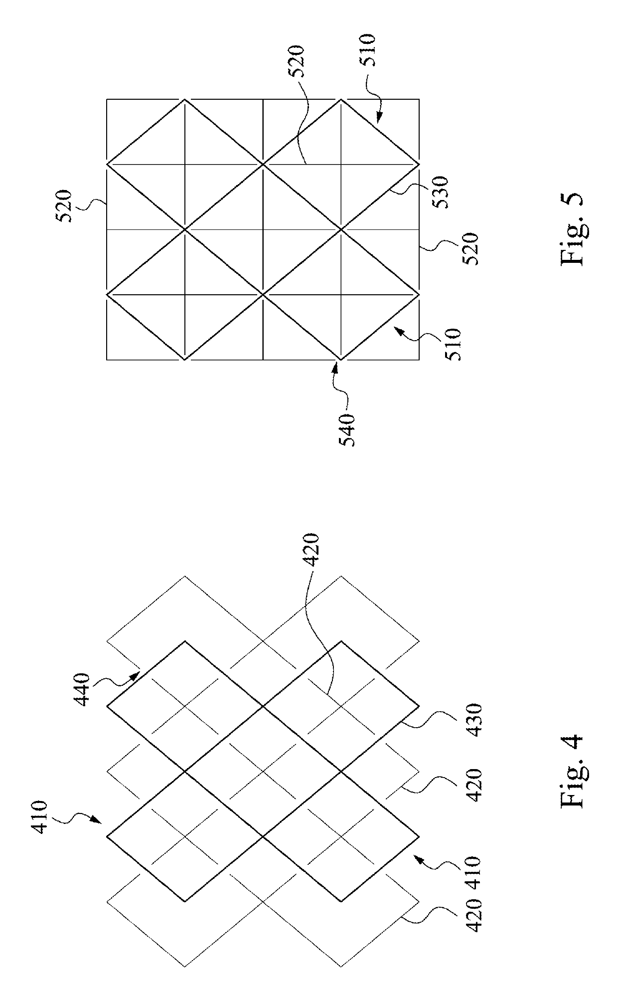
The present disclosure provides a touch panel structure, which includes a conductive channel region and a second dummy metal pattern. The conductive channel region includes a metal mesh and a first dummy metal pattern. The metal mesh is a conductive channel. The first dummy metal pattern is intersecting the metal mesh and has at least one breakpoint at every point of intersection with the metal mesh. The metal mesh is separated from the first dummy metal pattern to be insulated from the first dummy metal pattern at the at least one breakpoint. The second dummy metal pattern is disposed on the both sides of the conductive channel region.

Description

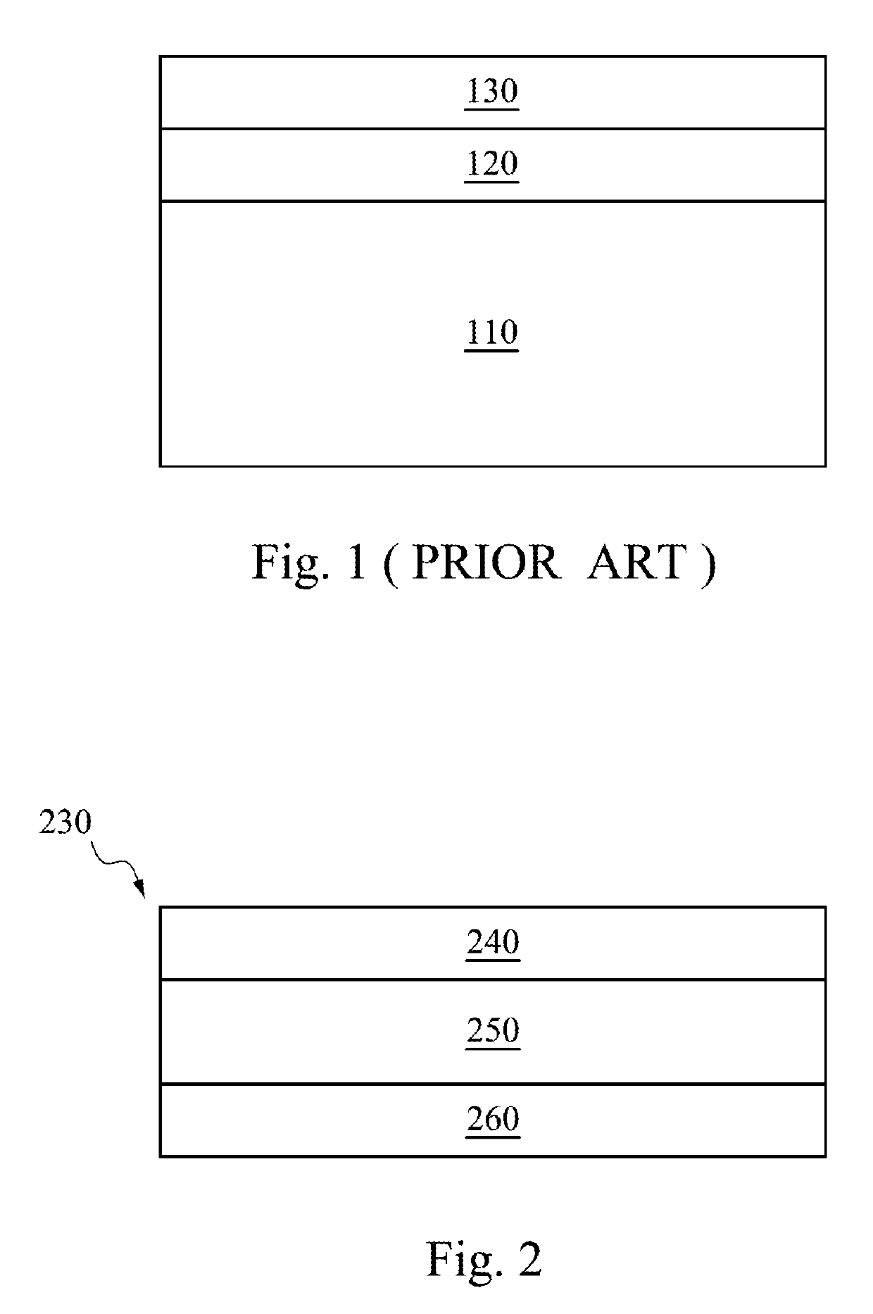
CROSS-REFERENCE TO RELATED APPLICATION[0001]This application claims priority to Chinese Application Serial Number 201710941834.6, filed Oct. 11, 2017, which is herein incorporated by reference.BACKGROUNDField of Invention[0002]The present invention relates to a touch panel structure. More particularly, the present invention relates to a metal mesh touch panel structure.Description of Related Art[0003]As electric products rapidly developing, touch devices are widely used in many kinds of products. As shown in FIG. 1, a touch device comprises a cover plate 110, an adhesive layer 120 and a touch layer 130, in which the touch layer 130 includes sensing electrodes.[0004]Nowadays, touch devices using metal meshes as sensing electrodes have been developed. A variety of touch assistant devices have been developed one after another with the growth of technology, for example, stylus pens, also associated with higher requirements of the touch identification accuracy. At present, the convention...

Claims


Application Information

Patent Timeline
Patent Type & Authority Patents(United States)
IPC IPC(8): G06F3/044G06F3/041
CPCG06F3/0445G06F3/0412G06F2203/04112G06F2203/04103
Inventor ZENG, JHE-WEIYANG, YUE-FENGCHEN, PO-LINLIU, JU-XIANGHUANG, YEN-HENG
Owner INTERFACE TECH CHENGDU CO LTD
Learn More